
e. Place the three-fourths inch aluminum block on the tabletop,
place the test tool on top of the attenuator, and use the fluoroscopic control.
(1)
Align the orientation marker "R" in the upper quadrant of the viewed
image.
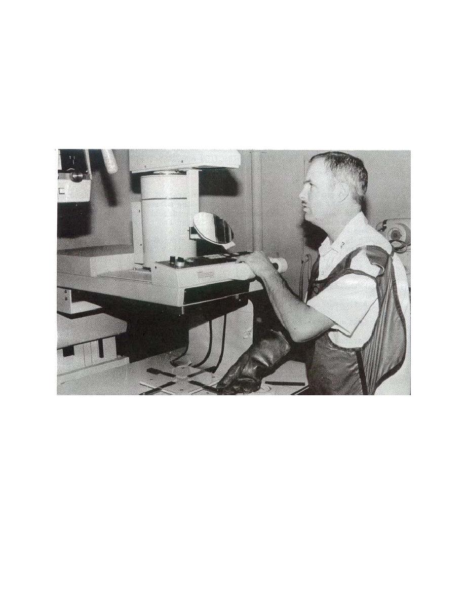
(2) Locate the test tool control dot at the approximate center of the viewed
fluoroscopic image (see figure 5-6).
Figure 5-6. Technologist locating the control dot under the fluoroscope.
f. Use the fluoroscopic unit, the manual mode, to accomplish the following
actions:
(1)
Achieve the final centering.
(2) Reduce the field in transverse (cross) dimension until the visual field
equals the row of dots in the test tool. Be sure to align the row of dots in the visual field.
g. Repeat the above procedure in the longitudinal (lengthwise) dimension.
MD0062
5-7

 Previous Page
