
(2)
Zero crossing.
(a) The zero crossing detection circuit uses two opto-isolators
connected in anti-parallel. Resistors R7 and R8 are current limiting resistors, and are
connected directly to the incoming power line. The opto-isolator's output circuit are
emitter followers. When L1 of the power line is positive compared to N, the led in U4 is
high and current flows through the opto-transistor, causing U3 pin 3 to be logic true.
(b) Conversely, when L2 is negative with respect to N, U5 conducts
and U3 pin 5 is logic true, and U3-3 is low.
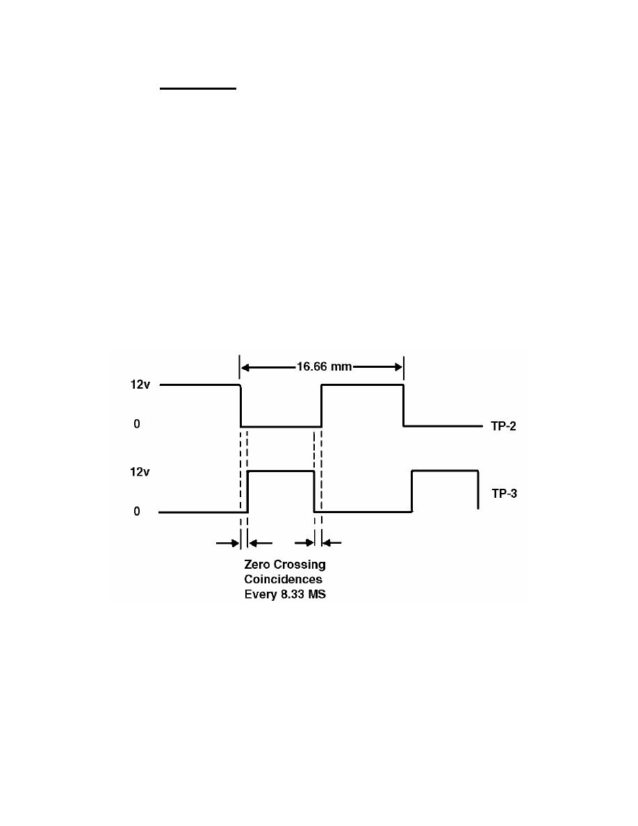
(c) The two successive stages of U3, a CMOS Schmidt trigger inverter
gate produces a signal with sharp logic transitions. See figure 4-4.
(d) Zero crossing is defined as the coincidence of TP2 and TP3 of the
power board both being logic low. This signal goes to the temperature board where
U12, a 4-wide NOR gate, looks for this coincidence, as well as its power burst signal
and thermistor check signals.
Figure 4-4. Power board zero crossing circuit.
MD0359
4-10

 Previous Page
