
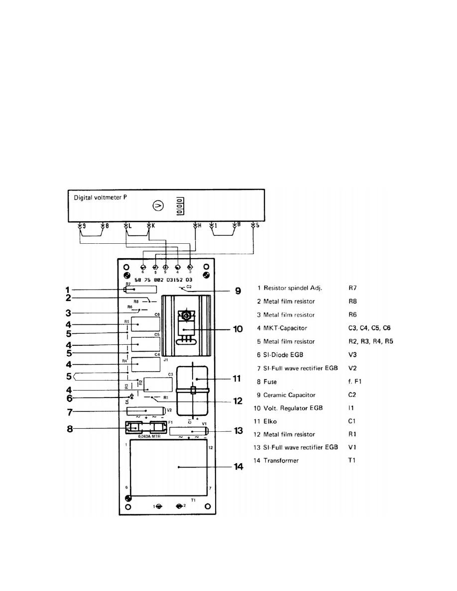
k. Digital Voltmeter "P" Printed Circuit Board D3. Refer to figures 2-6 and
3-11 for printed circuit board D3.
(1) The digital voltmeter "P" receives a rectified filtered 12.5v measuring
voltage, proportional to a 125v line voltage input. The power supply to the instrument
consists of the transformer T1 (D3) and a 5 volts direct current (vdc) circuit.
(2) The transformer T1 (D5) supplies a line voltage proportional voltage.
This stabilized voltage is supplied to the Schmitt trigger. The Schmitt trigger controls
the respective leds red (RT), green (GN), and yellow (GE) via gates J3 and J4. If there
is an over voltage condition, the Schmitt trigger J5 output drives transistor V9 and relay
AR 1 energizes interrupting the exposure circuit.
Figure 3-11. Pcb D3.
MD0361
3-12

 Previous Page
