
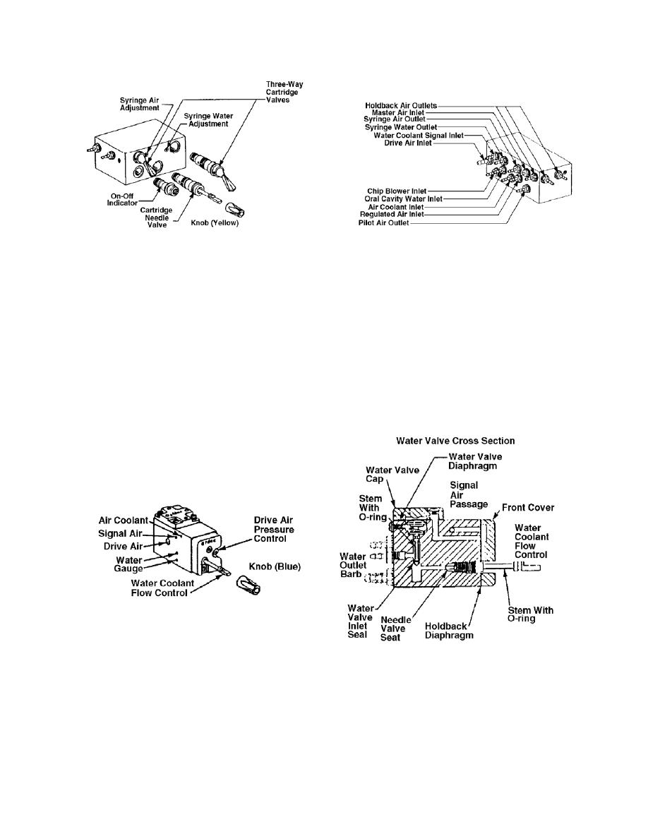
Figure 4-2. Master block assembly.
b. Control Blocks. The control block, in both the automatic and manual
systems, controls the routing of air and water coolant and drive air to the handpieces.
The control blocks are used in conjunction with the master block and either a manual
selector valve or a set of automatic handpiece hangers, to make a complete control
system. Refer to figure 4-3.
(1) Each of the control blocks has laterally drilled passages for drive air,
water coolant, air coolant/chip blower, and signal air. These passages line up with the
outlet passages in the end of the master block.
Figure 4-3. Control blocks.
MD0371
4-5

 Previous Page
