
4-18. BAFFLE GREASE TRAPS
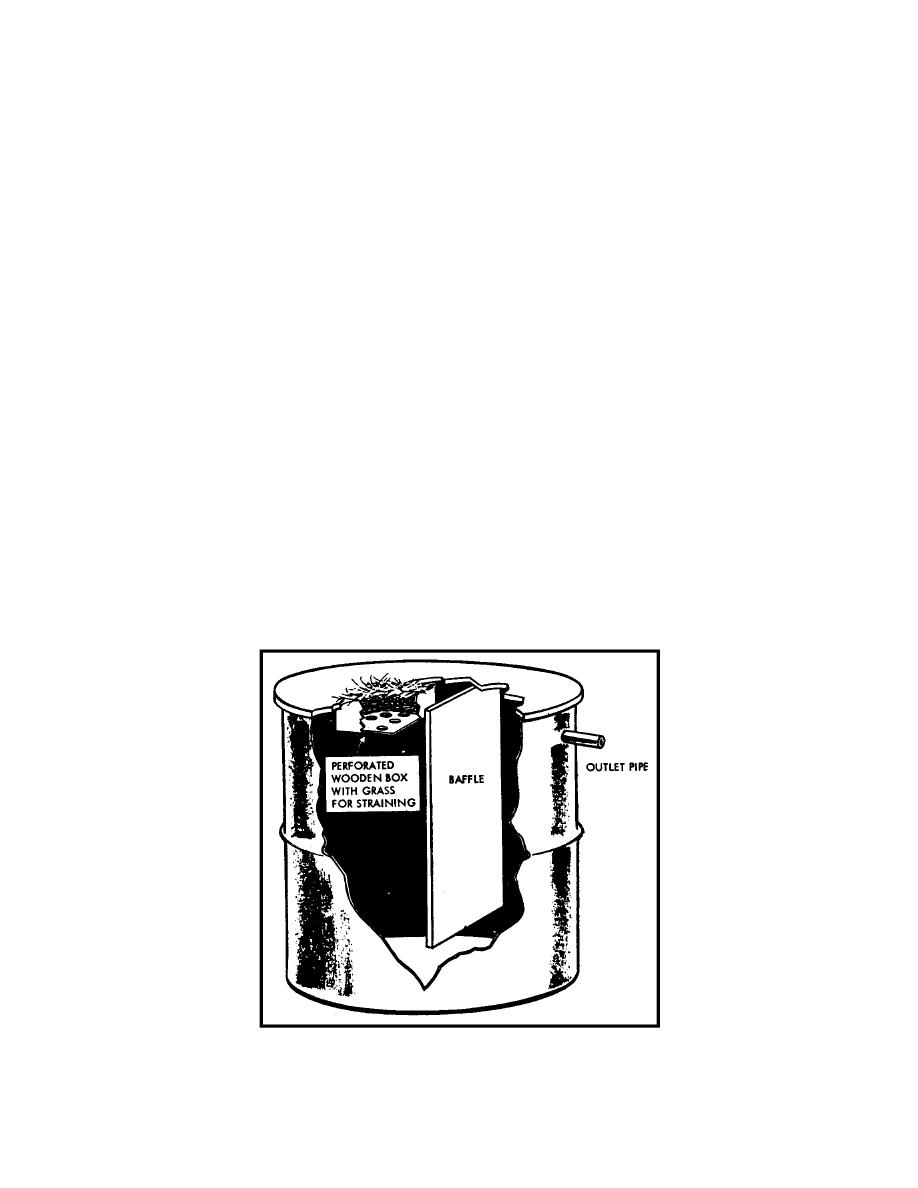
a. Constructing the Trap. A baffle grease trap may be made from half of a
barrel that has been cut in two (figure 4-13) or from a box (figure 4-14). The barrel or
box is divided vertically into unequal chambers by a solid wooden baffle. The baffle
extends from the top of the trap to within one inch of the bottom. The larger chamber
should contain about two-thirds of the capacity of the box or barrel. This larger chamber
should have a removable lid and a removable strainer. The strainer may be a box with
holes in the bottom that is filled with straw or burlap. The strainer removes coarser
solids. A one-inch pipe, inserted about three to six inches below the top of the smaller
(exit) chamber, acts as an outlet to carry the liquid from the trap to the soakage pit.
b. Operation. Fill the chambers with cool water. Pour the wastes through the
strainer to remove coarse solids. As the warm liquid strikes the cool water, the grease
rises to the surface of the entrance (large) chamber and the liquids runs under the baffle
to the exit (small) chamber. The outlet pipe carries the liquid from the trap to the
soakage pit or soakage trench. To ensure proper operation of the trap, it must be
cleaned frequently. Grease must be removed, the trap drained, the strainer cleaned,
and the sediment in the bottom removed. The removable strainer may be cleaned by
scrubbing the box with soap and water and filling it with new straw or burlap. The
grease, sediment, and straining material should be either burned or buried.
c. Size. The grease trap should be of sufficient capacity so that the hot, greasy
water being added will not heat the cool water already present in the trap to the point
where the grease will remain uncongealed and will pass through the trap.
Figure 4-13. Barrel-type baffle grease trap (cut-away view).
MD0535
4-18

 Previous Page
