Home
Download PDF
Order CD-ROM
Order in Print
Home
>
Medical Reference and Training Manuals
>
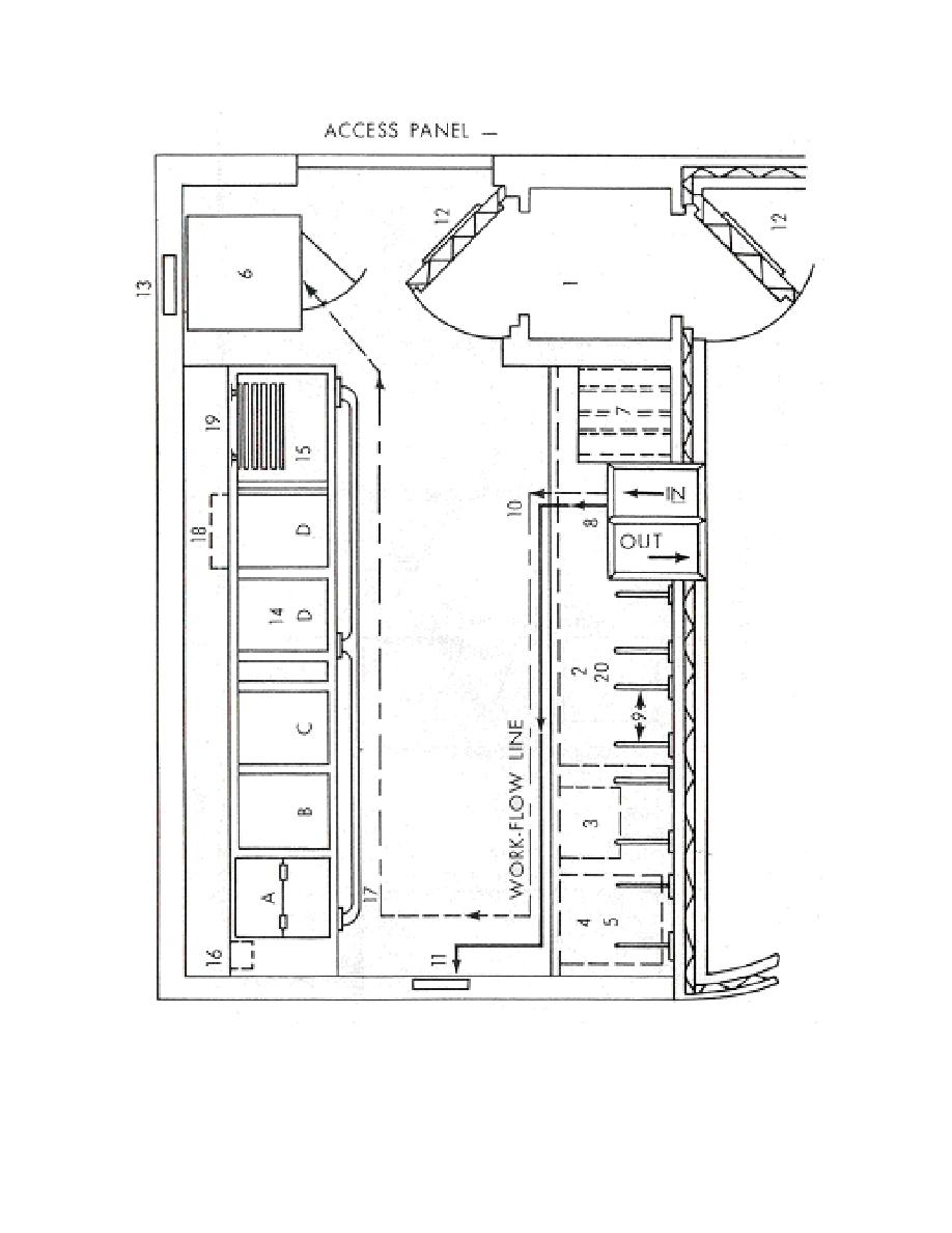
> Figure 2-2. Plan for a processing room showing tank and loading bench sections. - X-Ray Film Processing
Figure 2-1. A schematic diagram of an automatic processing darkroom and adjacent light room area. - X-Ray Film Processing
Figure 2-3. Diagram of typical entrance maze. - X-Ray Film Processing
X-Ray Film Processing
Page Navigation
20
21
22
23
24
25
26
27
28
29
30
NOTE
:
Dotted
workflow
line
indicates
course
of
exposed
film
during
the
processing
procedure.
Figure
2-2.
Plan
for
a
processing
room
showing
tank
and
loading
bench
sections.
MD0954
2-4


 Previous Page
