
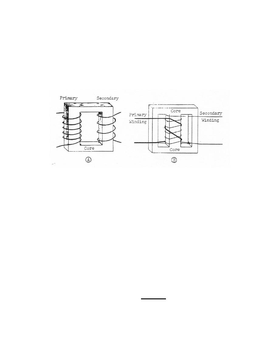
b. Shell-Type. The shell-type transformer (figure 2-17B) is considered the most
efficient. Such transformers are used in transmitting commercial power. The core of
the shell-type transformer is made of laminated silicon steel sheets placed on top of one
another. The coils are wound around the central section of the core. Since the primary
and secondary coils are wound close together around the core, the windings must be
highly insulated. A special insulating material is coated on the wires of both coils. For
the high voltage used in x-ray, the entire transformer is immersed in a container filled
with a special insulating oil or gas. The insulating oil also helps to cool the transformer
during operation.
Figure 2-17. Transformers. (A) closed-core type. (B) shell-type.
2-28. TRANSFORMER LOSSES
a. Resistance Losses. These losses are due to the normal resistance of the
wires that make up the primary and secondary windings of the transformer. This type of
power loss can be cut down by using copper wire of sufficiently large cross-sectional
area to reduce the resistance.
b. Eddy Currents. Eddy currents induced in the core cause the core to heat,
resulting in power loss in the transformer. To reduce eddy currents to a minimum, the
material making up the transformer core is laminated and each strip is sprayed with an
insulating coating.
c. Hysteresis. Since the use of AC causes a rapidly changing magnetic field,
there is a continuous reversal of the magnetic polarity in the core of the transformer.
The tiny magnetic particles in the core are constantly shifted around, arranging
themselves first in one direction and then in another, resulting in the development of
friction between the molecules, which produces heat in the core. Since the electrical
energy required to shift the molecules around must come from the primary current,
some electrical energy is wasted. This loss, hysteresis, can be lessened by using a
core material of high permeability.
MD0950
2-26

 Previous Page
