
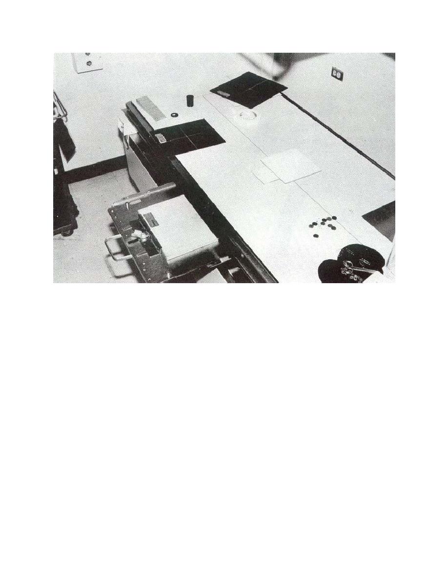
Figure 10-2. Lead shield over center hole exposing outer hole on test tool.
NOTE:
The density measurement of the central hole should be in the range of 1.5 to
2.5. As you repeat the filming, adjust the mAs until this reading is obtained.
The central hole should be densest because the beam defrays at an angle.
10-4. EVALUATION AND INTERPRETATION
a. In order to evaluate, you must measure and record:
(1)
The density of each hole image.
(2)
The required information on the data form.
b. A properly aligned grid's central hole will display the maximum density.
(1)
An acceptable tolerance is .5 inch from the central hole.
(2) An unacceptable tolerance will display a maximum density at 1 inch or
greater from the central hole.
c. If tests are unacceptable, repeat them to determine if you need corrective
maintenance.
MD0062
10-4

 Previous Page
