
CIRCUIT BREAKERS, CIRCUIT FUNCTION DESCRIPTION 1.2
2-4.
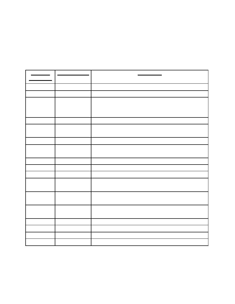
Refer to figure 2-3. All electronic circuits in the X-ray system are protected by the
extensive use of circuit breakers. In some instances, fuses are also used in conjunction
with circuit breakers as required by certification laboratories. All circuit breakers and
fuses in the main control are located on the left side panel when facing the front. The
following table lists each circuit breaker by number and the circuit it protects.
CIRCUIT
DESCRIPTION
FUNCTION
BREAKER
CB1
230v
230vac buss.
CB2
H2F
230vac to rotor control.
CB3
115v
115vac buss, constant voltage transformer (CVT), fan,
high voltage generator, kvp meter circuit, and ma-
meter circuit.
CB4
60v
60vac to rotor control.
CB5
24v
24vac ma-meter circuit, light circuit, impulse timer,
exposure circuit and exposure-end circuitry.
CB7
24BT
24vac to back-up timer.
CB9
115F
115vac to exposure circuit; ma, kvp, and time-limiting
circuit; autotimer selector; and ma-overload circuit.
CB10
15IT
115vac to impulse timer.
CB11
15MS
115vac to mas-meter circuit.
CB12
XSP
115vac from CVT to filament circuit.
CB14
QF
Voltage from wiper of fluoro variac (AF) to fluoro
damping resistor (5Ω 100w).
CB17
T1A
Voltage from autotransformer A3 to one side of
auxiliary power transformer.
CB18
T2L
Voltage from autotransformer A14 to one side of the
auxiliary power transformer.
CB23
AMW
One side of supply to the kvp meter circuit.
CB24
ACKM
One side of supply to kvp meter circuit.
CB26
L1F
One side of line to MAINS switch (CFD 1.0).
CB27
L2F
One side of line to MAINS transfer relay (CFD 1.0).
MD0351
2-8

 Previous Page
