
(2)
Plug in the analyzer and turn it on.
(3)
Set the mode switch to SELF TEST.
(4) The display should read 1000 +/-20, and the current source active lamp
should be on.
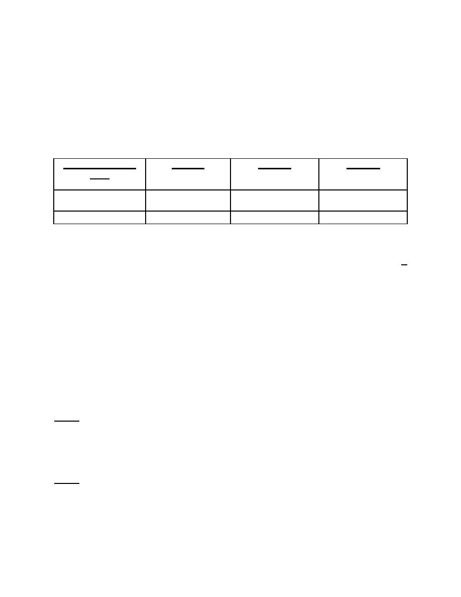
b. Check the Power Supply System Voltage. Refer to figure 2-1 for acceptable
voltage readings. Perform the following steps:
L-1--L-2
POWER SYSTEM
L1-GND
L2-GND
VAC
120vac (isolated)
120vac 20%
45-55% of L1-L2
45-55% of L1-L2
120vac (nonisolated)
120vac 10%
5% of K1-L2
120vac 10%
Figure 2-1. Acceptable measured voltage readings.
(1)
Set the mode switch to L1-L2. The display should now read line voltage +
10 percent.
(2) Set the mode switch to L1-GND. The display should read no more than 5
percent of L1-L2 (line voltage) on the grounded power system. For a properly balanced
isolated system, the reading should be about the same as the L2-GND reading.
(3) Set the mode switch to L2-GND. This should read about the same as the
L1-L2 reading for a grounded system. For an isolated system, it should read about the
same as the L1-GND.
(4) If the receptacle is wired backwards (reverse polarity), L1-GND instead of
L2-GND will be about equal to L1-L2. If the ground is open, L1-GND and L2-GND will
both be zero volts.
NOTE:
Contact the Directorate of Engineering or other appropriate authority to repair
the power system if it fails the power system voltage test.
c. Check the Power Cord Ground Resistance of the Unit Under Test. Refer to figure 2-2.
Perform the following steps:
NOTE:
This procedure does not apply to equipment that is hardwired to the power such
as x-ray or sterilizing equipment. For this equipment, you must use the external
ground resistance testing procedure. See paragraph e below for external
testing procedures.
MD0356
2-3

 Previous Page
