
b. Temperature Control Board Function. Refer to figure 4-2.
(1) Ramp generator. The temperature control board senses an error
voltage that is produced by comparing the thermistor/set point voltage with the
proportional control ramp.
(a) One of the zero crossing signals from the power board is connected
to a 4024 binary counter (U5). A series of weighting resistors is connected to the
outputs of U5. These resistors are, in turn, connected to the current summing input of
U6, pin 2. The resistors are in a binary sequence, and generate a staircase ramp.
1 There are seven bits forming this ramp.
2 At the end of the full count, the counter is not reset, but instead
begins to count down because of its overflow and generates a ramp.
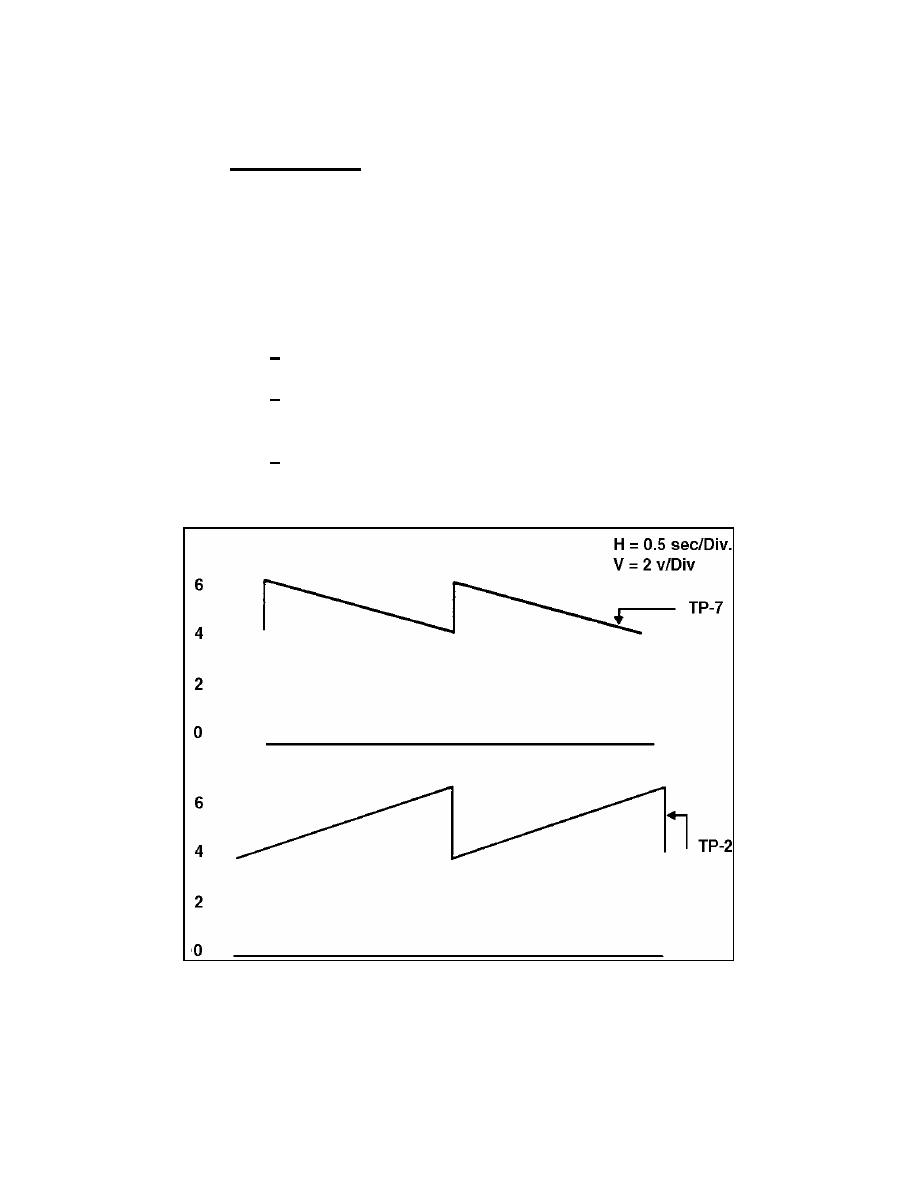
3 At TP-7, you can check the amplitude of the ramp, and adjust
R1 for 2 volts peak to peak. The ramp runs between 4 and 6 vdc, with a period of 2
seconds. Refer to figure 4-6 to see the wave form.
Figure 4-6. Temperature board wave forms.
MD0359
4-12

 Previous Page
