
(3) You cannot measure the tube current between the points X and Y since
an alternating current flows there (tube current plus capacitor-charging current). Thus,
the diodes V2 and V3 have short circuited the capacitor charging current in the tube
current measuring circuit. You may measure the tube current between points
D1.9/D1.10. Refer to figure 3-8.
Figure 3-8. Heliodent 70 secondary circuit.
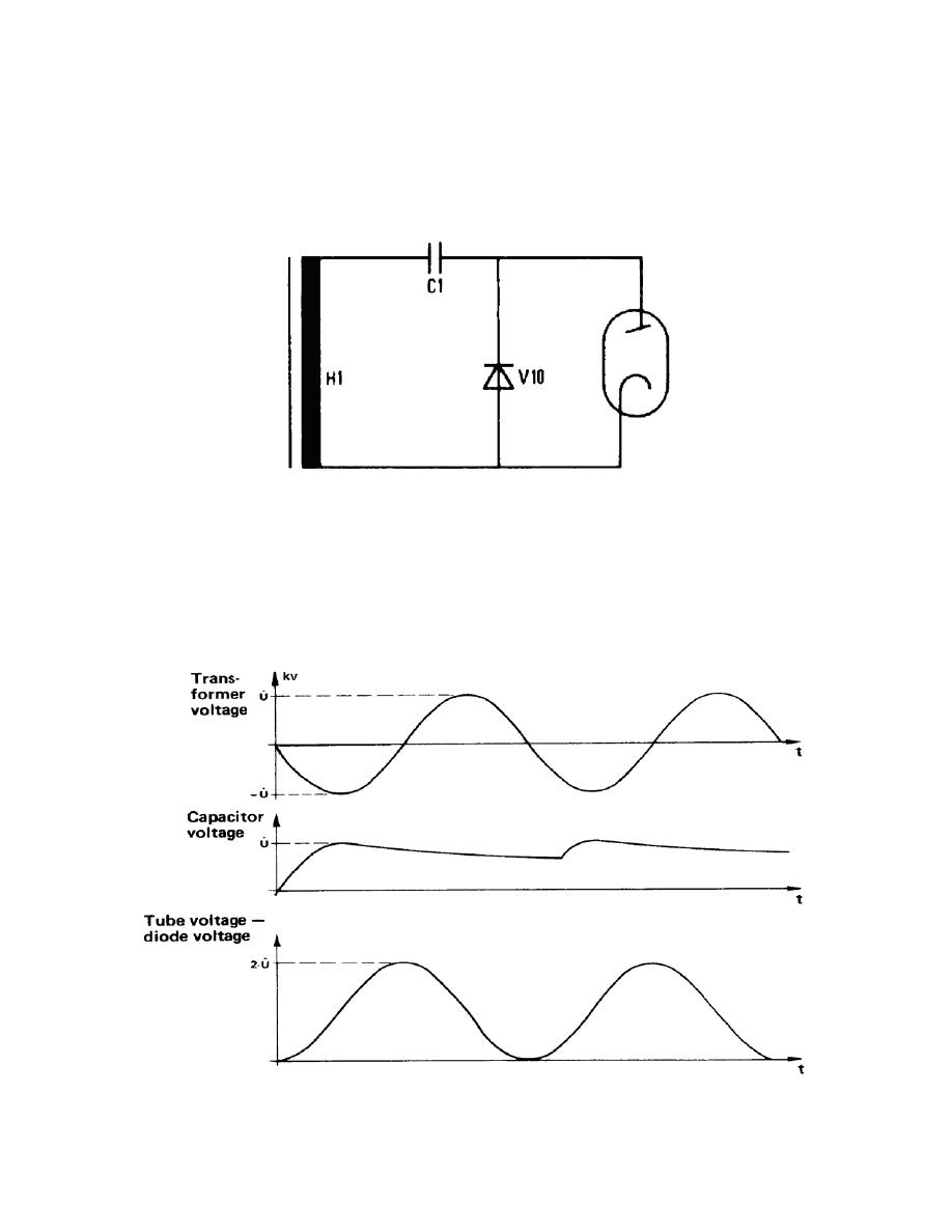
b. Heliodent 70. The secondary circuit of the Heliodent 70 consists of a
voltage-doubling circuit (C1, V10, H1). The negative half wave of the transformer
voltage charges the capacitor C1. The positive half wave of the transformer voltage is
added to the capacitor voltage, so that twice the transformer peak voltage is required on
the tube. Refer to figure 3-9.
Figure 3-9. Transformer peak voltage doubling.
MD0361
3-8

 Previous Page
