
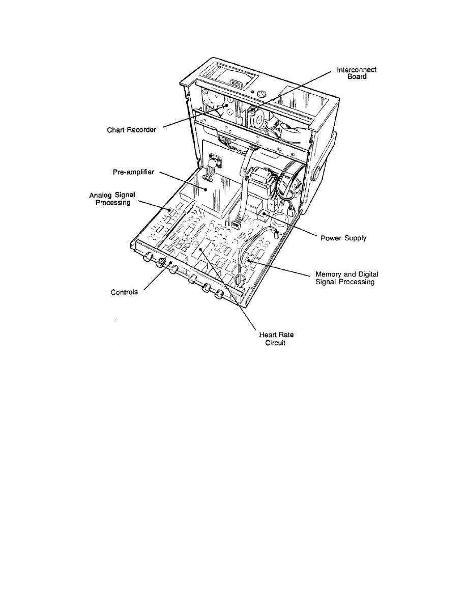
Figure 1-10. Monitor circuit board.
b. Calibrate the Preregulator. Refer to Appendix E, Monitor Board Power Supply
Schematic, section D-23.
(1)
Plug the unit into a 120v 60Hz power line and turn it on.
(2) Clip on one voltmeter probe to the collector of Q41 and the other to a
ground. The power supply heat sink is a convenient ground point.
(3)
Adjust RA10 until the voltmeter reads 12.5 volts direct current (vdc).
(4) Check the regulation with low and high line voltage by powering the unit
from the variable line voltage transformer. Low line voltage is considered 100 volts
alternating current (vac) root-mean-square (RMS), and high line is 130v.
(5) With the unit turned on, the preregulator voltage should not change by
more than 200mv in either direction. With normal line 117vac, turn on the chart recorder.
The 12.5v should not drop below 12.1.
MD0362
1-13

 Previous Page
