
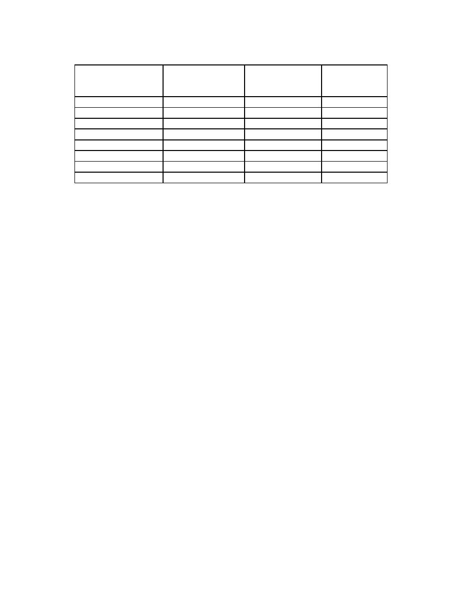
DELIVERED
STORED
VOLTAGE
TIME (MSEC)
JOULES
JOULES
VOLTS
360
455
1355
17.0
200
342
1170
12.0
100
172
830
12.0
50
82.6
575
12,0
30
48.4
440
12.0
20
34.2
370
12.0
10
18.2
270
12.0
5
10.0
200
12.0
Table 2-1. Stored energy versus delivered energy at the critically selected voltages.
h. Functions of the Circuits in the Transthoracic Load Compensation.
(1) Since the source impedance of a defibrillator is fixed, the energy delivered
to the load is highly dependent on the load impedance. Many defibrillator are not able to
deliver the selected energy to a load which differs from the load impedance which was
assumed in the design.
(2) The patented MRL transthoracic load compensation overcomes this
difficulty by varying the discharge pulse width to compensate for rather wide variations in
actual load impedance. This circuit will be discussed under the heading of primary dump
circuit.
i.
Functions of the Circuits in the Ready Lite Circuitry.
(1) The ready lite circuit, which is initiated by the previously explained outputs
from the various high-voltage regulators, not only inhibits further charging, but also is used
to turn on transistor Q3. This turns on the various ready lamps and also supplies an input
to the fire control IC, U15, which only then allows firing and delivery of energy to the load.
(2) This is a form of a low voltage safety circuit because of inability to fire until
the voltage is high enough to deliver the selected energy.
j.
Functions of the Circuits in the Fire Circuitry.
(1) When the ready circuit has supplied its signal, and there is no command
from the synchronizer (to be explained later), the machine can be fired by depressing both
fire switches simultaneously. This completes the inputs to the fire control chip, and pulls
the reset pin on U14 high.
MD0362
2-30

 Previous Page
