
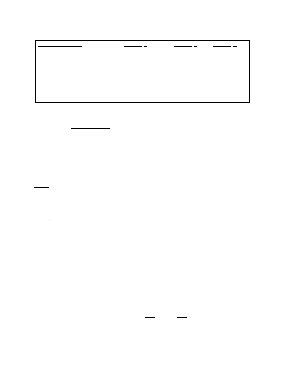
Static Vacuum of
10cmH20
20cmH20
60cmH20
Flow @ pump inlet
120 lpm
160 lpm
280 lpm
Flow w/glass bottles &
4 ft 3/8 in ID tubing
32 lpm
55 lpm
95 lpm
Flow w/disp. bottles &
6 ft 3/8 in ID tubing
35 lpm
55 lpm
100 lpm
Table 1-1. Approximate flow rates.
Vacuum testing. Perform the following procedures to test the vacuum.
(4)
(a) Use a 4 foot piece of 3/8 inch tubing and a water manometer that
measures at least 0 to 70cmH20 or a mercury manometer capable of measuring a
vacuum of 0 to 50mmHg.
(b) Connect the manometer to the patient connection part via the
tubing.
The manometer should read 0cmH2O.
NOTE:
(c) Turn the Emerson 55 JS on and slowly rotate the suction dial from
the MIN position clockwise to the MAX position.
NOTE:
While rotating this dial, the manometer level should rise as the vacuum
increases. Within 10 seconds of reaching the MAX setting, the manometer
should read 60cmH2O (44mmHg). The vacuum indicator on the front panel
should read 2cmH2O of what the H2O manometer reads across the full
range of settings on the suction dial.
1-5.
CIRCUIT EXPLANATION
Refer to figure 1-1 as we begin to trace the electrical circuit with the white wire
also known as the neutral or ground wire.
a. The white wire from the wall outlet to the convenience outlet.
b. Through convenience outlets 3 and 4 to tie point A.
c. From tie point A to the pilot light 2, and to A1-1, and to M1-2.
MD0365
1-6

 Previous Page
