
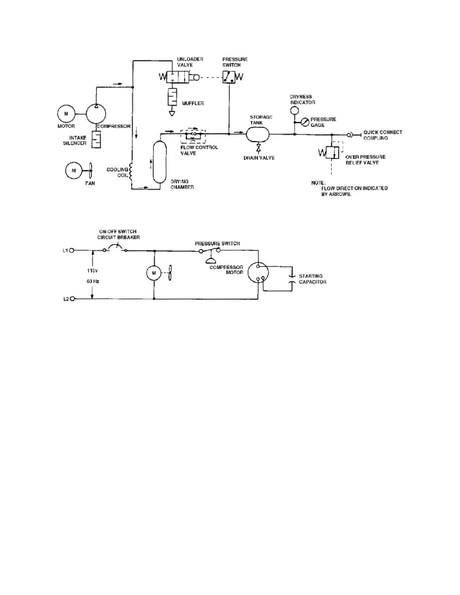
Figure 1-3. Pumping cycle schematic diagram.
(1) When you set the circuit breaker to ON, both the compressor and the
cooling coil fan motor start.
(2) The compressor directs compressed air through the cooling coil, the
drying chamber, and the flow control valve into the storage tank.
(a) The drying chamber contains a desiccant to remove moisture from
the air.
(b) The flow control valve contains a ball check valve to allow
compressed air to enter the storage tank while preventing it from leaving during the
pumping cycle.
(c) The pressure gauge on the storage tank indicates the internal air
pressure within the tank.
(d) The dryness indicator shows the presence or absence of moisture
in the stored compressed air by its color (blue for dry, pink for wet).
MD0366
1-7

 Previous Page
