
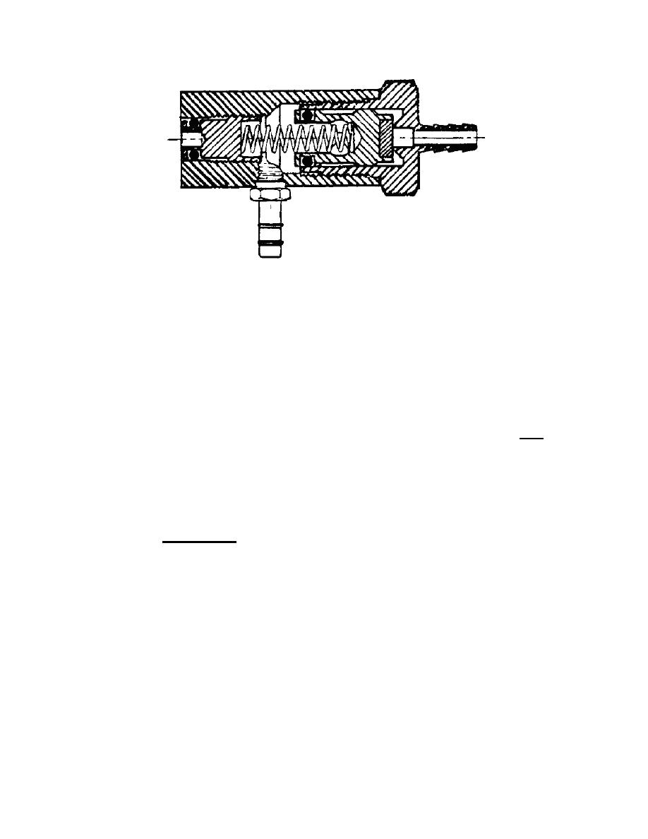
Figure 1-4. Flow-bypass valve.
(a) Another outlet from the tee fitting is connected to an adjustable
needle valve used to control maximum and minimum flow to the nebulizer/humidifier jet.
With the nebulizer control turned to MAX (valve closed), the jet orifice is subjected to
the full flow provided by the regulator. The nebulizer jet cannot accommodate full flow,
so the bypass valve opens against spring tension and directs the excess flow to the
auxiliary flow socket.
CAUTION:
The auxiliary flow power line must never be restricted. DO NOT USE
THIS GAS FLOW SOURCE TO POWER THE NEBULIZER JETS. The
entire calibrated flow system is balanced to the micro-nebulizer only.
(b) A third outlet from the inlet manifold delivers source gas to the mode
selector, a two-piston rotary control valve which selects the mode of operation in which
the ventilator is to be used. One position is labeled CONTROLLED IMV and the other is
SPONTANEOUS BREATHING.
(4) Mark 2 servo. The Mark 2 servo (figure 1-5) functions only in the
controlled intermittent mandatory ventilation phase and has two controls. One control
sets inspiratory time, the other sets expiratory time. The servo consists of a central
valve assembly called a "plunger." It operates between two diaphragms separating the
plunger from two timing chambers. When gas pressure is first supplied to the Mark 2
servo inlet, the right-hand disc (valve number 1) is closed and no gas flows from the
outlet. Gas will flow through the expiratory time control valve into chamber A, causing
pressure to build up since valve number 2 is closed. When pressure in chamber A is
strong enough to overcome the force of spring tension on valve number 1, the valve
opens and gas flows through the outlet. Gas also flows into timing chamber B, causing
pressure against the diaphragm to increase. Valve number 3 is closed by pressure from
valve number 1. When valve number 2 closes, pressure again builds up in chamber A
through the expiratory time control valve.
MD0355
1-6

 Previous Page
