
2-31. VALVE TUBE RECTIFICATION
The type of rectifying device most commonly used in the past was the valve tube
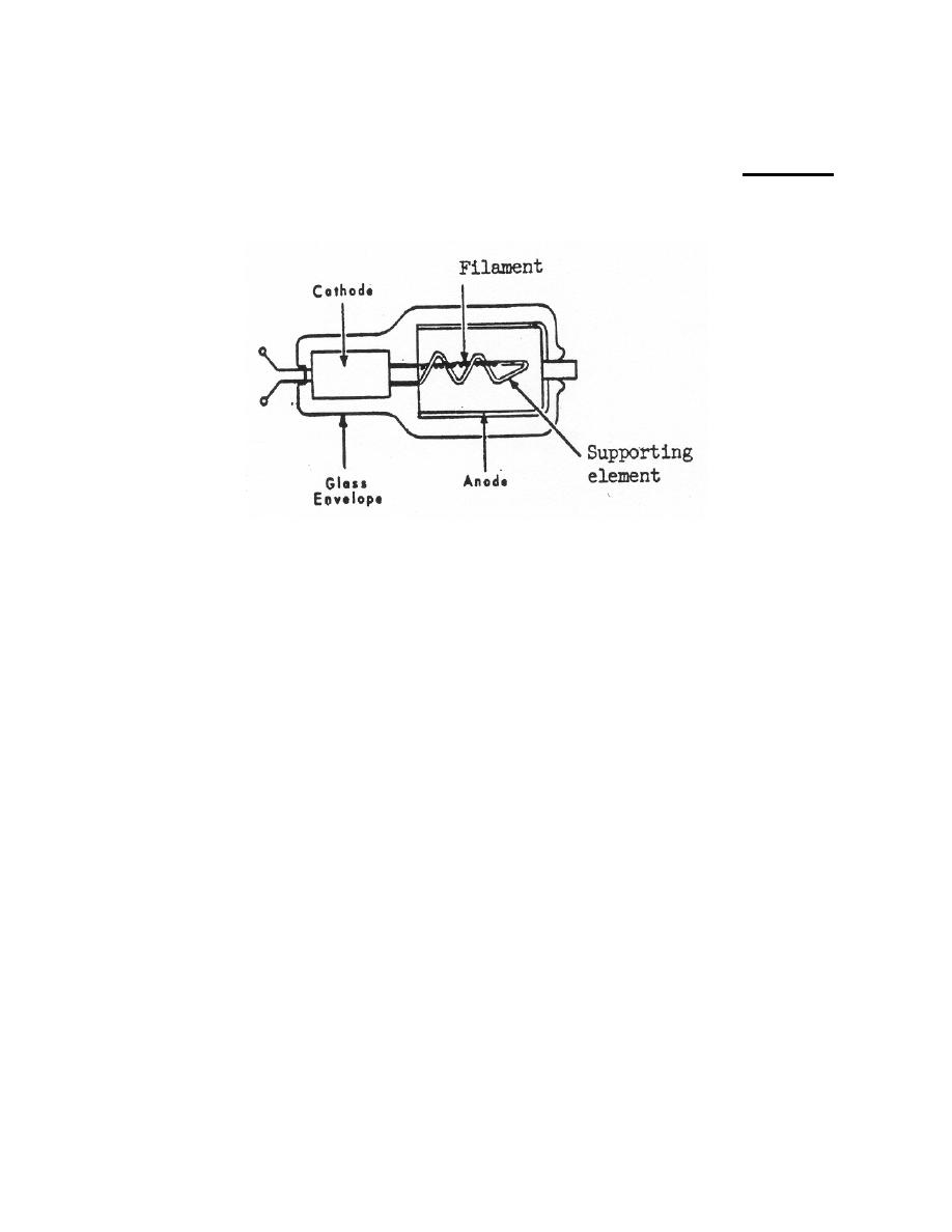
(figure 2-21). This vacuum tube works on the same general principles as x-ray tubes,
but differs in certain details of construction.
Figure 2-21. The valve tube.
a. Cathode. In a valve tube, the filament is a coil of tungsten wire that is both
longer and larger in diameter than the filament of an x-ray tube. The filament is
specially treated with thorium, making it possible for a greater number of electrons to be
liberated with a lower voltage filament current. The filament is supported by a spiral-
supporting element running into a hollow anode (figure 2-21). This arrangement makes
use of the full 360o of thermionic emission of electrons.
b. Anode. The anode has a large surface area and may be in the form of a
cylinder surrounding the filament. In operation, the electrons emitted from the hot
filament are attracted in all directions toward the entire surface of the anode.
c. Principles of Operation. The large thoriated filament, when heated to a high
temperature by the filament current, liberates a large number of electrons, many more
than are required to maintain current flow through the x-ray tube. Because of this
excess of electrons, the voltage drop across a valve tube is very small. With this small
voltage drop, the electrons cannot gain great speed and, therefore, do not have
sufficient energy to produce x-rays in the valve tube. However, if, for some reason such
as reduced electron emission from the filament, the forward resistance of the valve tube
increases to the point where this voltage drop becomes 12 kV or higher, the electrons
would be accelerated through the valve tube at a speed that would produce x-radiation
when they strike the anode. Valve tubes can be used to produce either half-wave or
full-wave rectification.
MD0950
2-30

 Previous Page
