
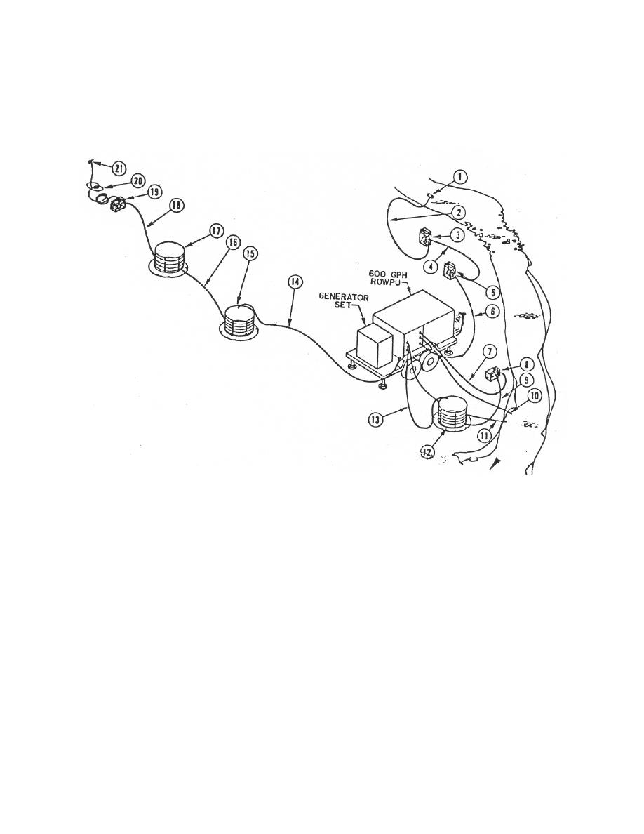
and a brief description of each number follows. Depicted in figure 5-18 is the equipment
included in the ROWPU. Illustrations of the ROWPU equipment components: raw
water, water distribution, backwash pumps, tubes and chemical feed pump, the entire
control panel, and the TOS meter are located in figures 5-19 Parts A, B, C and D.
1.
Float and strainer
8. Backwash pump
15. Collapsible 1,500
gallon tank
2.
Three inch, hard rubber hoses
9.
Backwash 2-inch, hard rubber hose16. Product water
1 inch, hard
rubber hose
3.
Raw water pump
10.
Wastewater 2-inch canvas hose
17. Collapsible 1,500
gallon tank
4.
Two 1 inch, hard rubber hoses 11.
Vent vessels
18. Product 1 inch,
hard rubber hose
5.
Raw water pump
12.
Collapsible 1, 500 gallon tank
19. Distribution pump
6.
Three 1, canvas hoses
13.
Brine 2-inch, canvas hose
20. Product water
1 inch, canvas
hose
7.
Backwash canvas hose
14.
Two 1 inch, hard rubber hoses 21. Distribution nozzle
Figure 5-16. Typical field ROWPU installation.
MD0160
5-27

 Previous Page
