
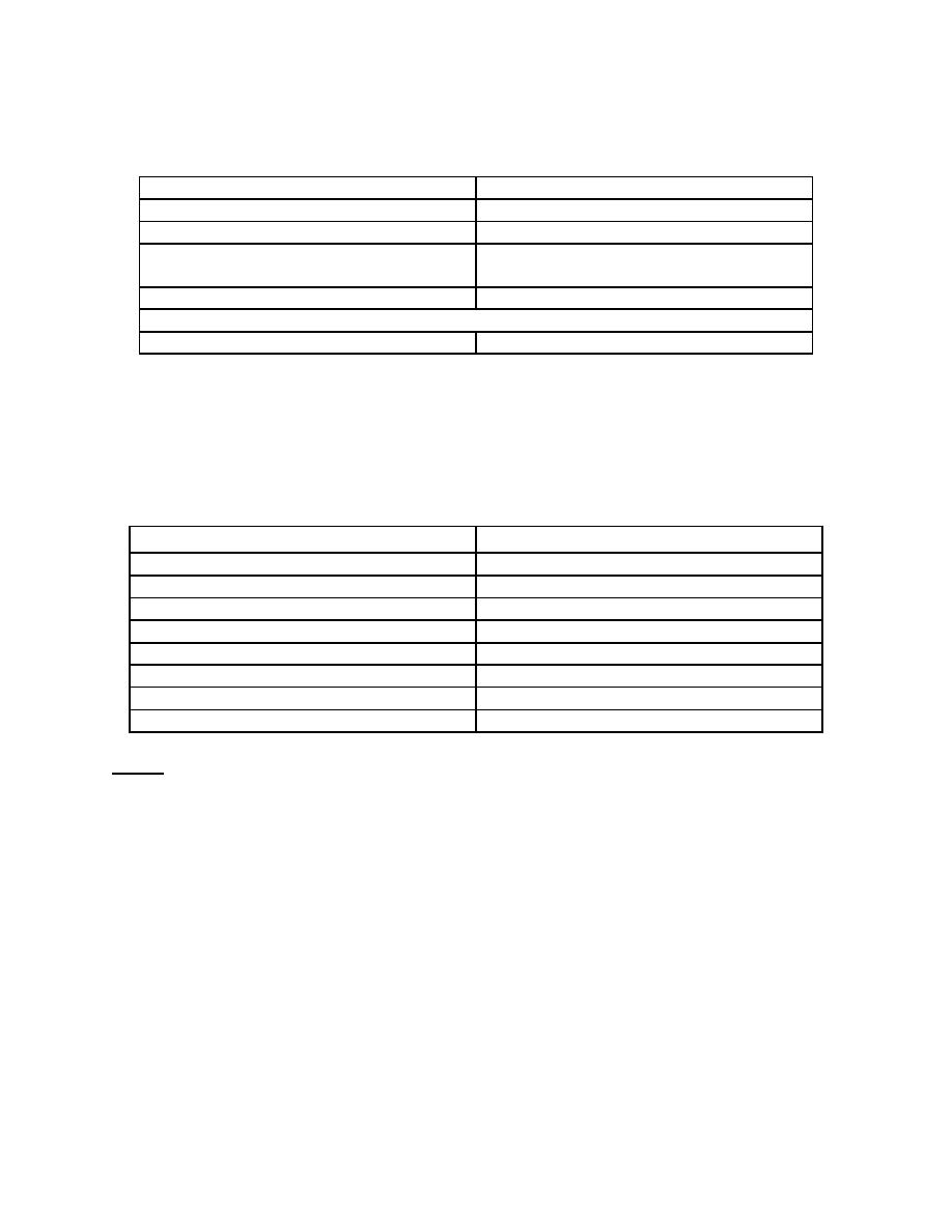
n. Final Test Switch Settings. At the end of this test procedure, be sure to set
the test switches as given in the following chart.
SW2-1
OFF
SW3-1
OFF
SW2-2
OFF
SW3-2
OFF
SW2-3
OFF
SW3-3
OFF
SW2-4
OFF
SW3-4
OFF
SW2-5 ON
SW3-5 OFF (Beam-Right Operation)
OR
SW2-5 OFF
SW3-5 ON (Beam-Left Operation)
o. Cassette Tray Adjustment. The collimator has been factory-calibrated
around a cassette tray which is calibrated at 500 ohms for an 11 inch (12 1/8 inch
outside) cassette. The 11-inch dimension represents exactly one-half of the 1K-ohm
cassette tray potentiometer. Check, and adjust if necessary, your cassette trays.
Consult the tray manufacturer's manual for adjustment procedures. The following is a
size vs ohms chart.
Cassette Size
Ohms between pins 1-5 and 4-8
5 inches
60 Ohms
7 inches
207 Ohms
8 inches
280 Ohms
10 inches
427 Ohms
11 inches
500 Ohms
12 inches
573 Ohms
14 inches
720 Ohms
17 inches
940 Ohms
NOTE:
With tilting tables, the table and wall cassette tray potentiometers must be set
exactly the same. This is because there is only one SID adjustment in the
collimator for a given distance to either Bucky.
1-9.
AUTOMATIC EXPOSURE CONTROL
Test the Expos-AID automatic exposure control (AEC) annually to see that it
meets the kvp range/optical density tracking specifications. If it does not, repeat the
calibration procedures. Also test the system whenever the X-ray generator is
recalibrated or there is a change in the screen-film combination used. Visually inspect
the Expos-AID cables for signs of wear. Check cable and PCB connectors to ensure
they are securely fastened.
MD0351
1-46

 Previous Page
