
(4) Deactivate the Stereo/Tomo switch. The collimator should return to the
state as indicated in step k (2).
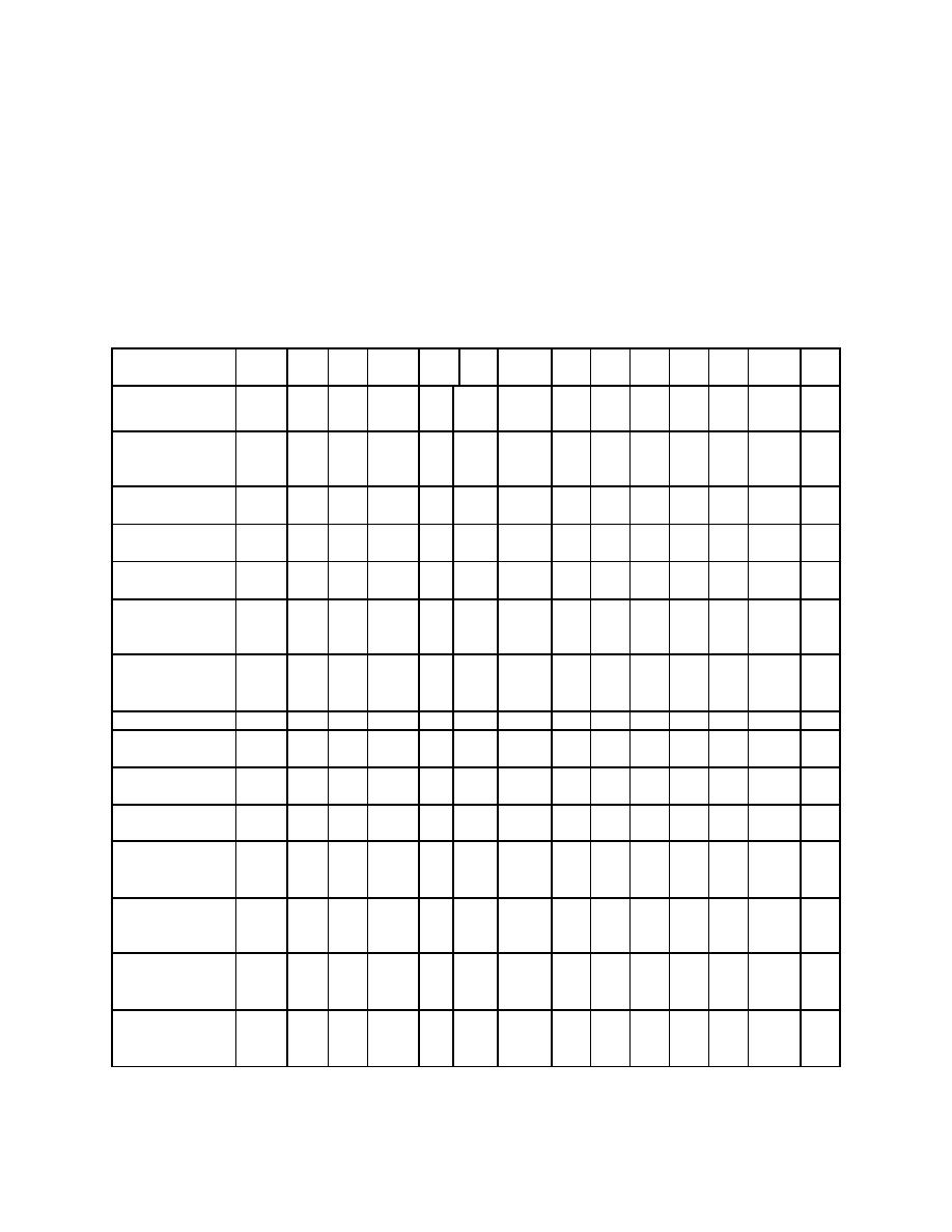
m. Input Signal Verification Chart. The charts in figure 1-9 are keyed to the
preceding steps and to the signal name appearing on the Logic PCB Schematic
70-08002. A "logic indicator" is located on the logic PCB. Attach a miniature test lead
clip on TP-1 and, by the use of a pointed probe, the logic (VIRC, IR, TRUE, VISID OUT,
VSID IN, AND VIRL signals are analog and cannot be expressed in "logic" terms) status
can be checked when necessary. A logic "HIGH" signal will illuminate LED-3 and a
logic "LOW" signal will not illuminate LED-3.
1-8e
(1)
(2)
1-8f
(1)
(2)
1-8g
(1)
(2)
(4)
(6)
(8)
1-8h
(2)
SIGNALS
(para ref.)
VIRC (TS4-7)
VIRL (TS4-5)
STEREO/
1
1
1
1
1
1
1
1
1
1
1
1
1
1
TOMO
(TS4-11)
C=0, T=0
0
1
1
0
1
1
0
0
0
0
0
0
0
0
(TS3-10)
C= +90
1
0
1
1
0
1
1
1
1
1
1
1
1
1
(TS3-6)
C= -90
1
1
0
1
1
0
1
1
1
1
1
1
1
1
(TS3-7)
C= +90,
1
1
1
1
0
1
1
1
1
1
1
1
1
1
T= +90
(TS3-9)
C= -90,
1
1
1
1
1
0
1
1
1
1
1
1
1
1
T= -90
(TS3-8)
IR TRUE
40" SID
1
1
1
1
1
1
1
1
1
0
1
1
1
1
(TS4-14)
72" SID
1
1
1
1
1
1
1
1
1
1
0
1
1
1
(TS4-9)
EXP.REL.RY
0
0
0
0
0
0
0
1
0
0
0
0
0
0
(TS4-8)
TABLE LEFT
1
1
1
1
0
1
1
1
1
1
1
1
1
1
SIDs
(TS4-17)
TABLE RIGHT
1
1
1
1
1
0
1
1
1
1
1
1
1
1
SIDs
(TS4-16)
WALL L/R
1
0
0
1
1
1
1
1
1
1
1
1
1
1
SIDs
(TS4-19)
VERT
0
1
1
0
1
1
0
0
0
0
0
0
0
0
SIDs
(TS4-10)
"X" = Don't Care "1"= Logic High (+15v)
"0" = Logic Low (0v)
Figure 1-9. Over-table logic chart.
MD0351
1-45

 Previous Page
