
(6)
Align the door. Refer to figure 1-15.
(a) Check that the side play clearance of the teflon guides within the
door guide channels are 1/32 to 1/16 of an inch (0.8mm to 1.6mm) when the door is hot.
Loosen the two channel bracket screws and move the bracket to obtain required Teflon
guide clearance.
(b) Ensure that the door is aligned and centered squarely with the
chamber. Measure from the door guide channel to the inside surface of the chamber.
The dimension should be within 1/32 to 1/16 of an inch (.8mm to 1.6mm). You can
attain adjustment by loosening the two screws in the door channel bracket and
movement of the bracket.
(c) Raise the door to position the upper edge between the lugs and the
headring. Clearance of the door plate from either surface should be 1/32 + 1/64 of an
inch (.8mm + .4mm). You can attain adjustment by loosening the hex nut that secures
the door guide channel to the channel bracket.
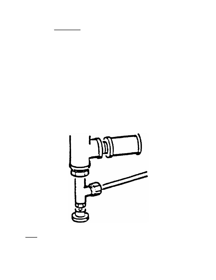
b. Adjust the Chamber Bleed Valve. You adjust the chamber bleed valve to
allow the liquid to evaporate without disturbing the liquid. Refer to figure 1-17.
Figure 1-17. Chamber bleed valve.
NOTE:
The setting of the chamber bleed valve in the liquid cool bypass line
determines the length of time required for releasing chamber pressure during
a liquids cycle.
MD0354
1-37

 Previous Page
