
(3)
Adjust the door switch. Refer to figure 1-16.
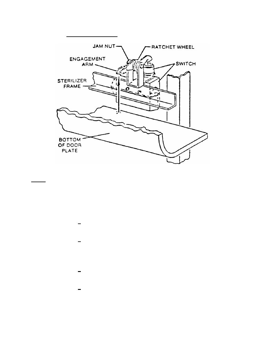
Figure 1-16. Door switch adjustment.
NOTE:
The door switch is located on the right surface of the front frame cross
member under the door. The control end door switch operation is identified
by the number 8 light on the relay board. The remote end operation switch is
identified by the number 9 light on the double door units.
(a)
Perform checks.
1 Raise the latch and control head to observe the relay panel
indicator lights.
2 Raise the door to the closed position. The SSR number 8 light
should come on just before the door latch locks on the latching bar.
(b)
Make adjustments.
1 Remove the lower face panel or the right side panel on cabinet
models.
2 Loosen the door switch jam nut.
MD0354
1-35

 Previous Page
