
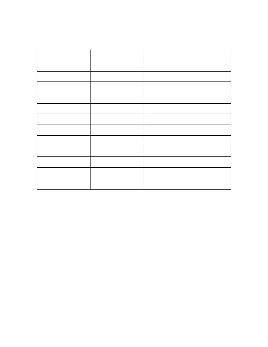
d. Solid State Relays (SSR) Functions. Refer to table 1-1 for a listing of SSR
functions when troubleshooting malfunctions.
SSR
TYPE
FUNCTION
0
Output
Jacket Temperature Control
1
Output
Chamber Temperature Control
3
Output
Chamber Drain
4
Output
Store Exhaust Water
5
Output
Water to Ejector
6
Output
Controls Direction of Door #0
7
Input
Indicates if Door #0 is Sealed
8
Input
Indicates if Door #1 is Closed
9
Input
Indicates if Door #1 is Closed
10
Input
Indicates if Door #1 is Sealed
11
Output
Controls Direction of Door #1
14
Output
Air In/Vent Valve
Table 1-1. SSR Functions
1-5.
OPERATION SEQUENCE
The following simplified explanations give you a general knowledge of cycle
functions for each type of cycle phase. Refer to figures 1-7 through 1-10. A more
detailed description is found in paragraph 1-6, Cycle Phase Description.
a. Solid State Relay Lights. Each action during a phase is indicated by
a numbered SSR light located in the panel control box. When an SSR light is on, the
corresponding solenoid valve should be energized. All two-way solenoids used in this
equipment are normally closed.
MD0354
1-13

 Previous Page
