
b. Disassemble the Rotational Parts. Refer to figure 4-9.
(1)
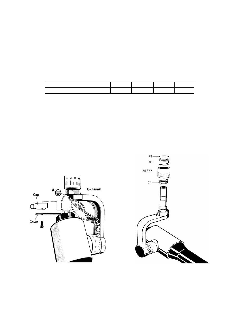
Remove the cap and cover.
(2)
Disconnect wires in the U-channel and ground wire (A). Refer to 4-9.
(3)
Remove the cover (23) shown in figure 4-8.
CAUTION:
The wires must be marked as follows below.
X-ray tube assembly wires
3
4
5
6
Scissors arm wires
3
4
5
6
(4)
Remove the countersunk screw from the bracket (22) shown in
figure 4-8.
(5)
Hold X-ray head at the yoke and remove the bracket (22). Remove the
X-ray head.
(6)
Remove the clip ring (78) as shown in figure 4-10.
(7)
Check the rotational stop assembly (3 parts: 74, 75/77, 76) as shown in
figure 4-10.
(8)
Replace parts as needed.
Figure 4-9. X-ray head removal, part two.
Figure 4-10. X-ray head removal, part three.
MD0361
4-14

 Previous Page
