
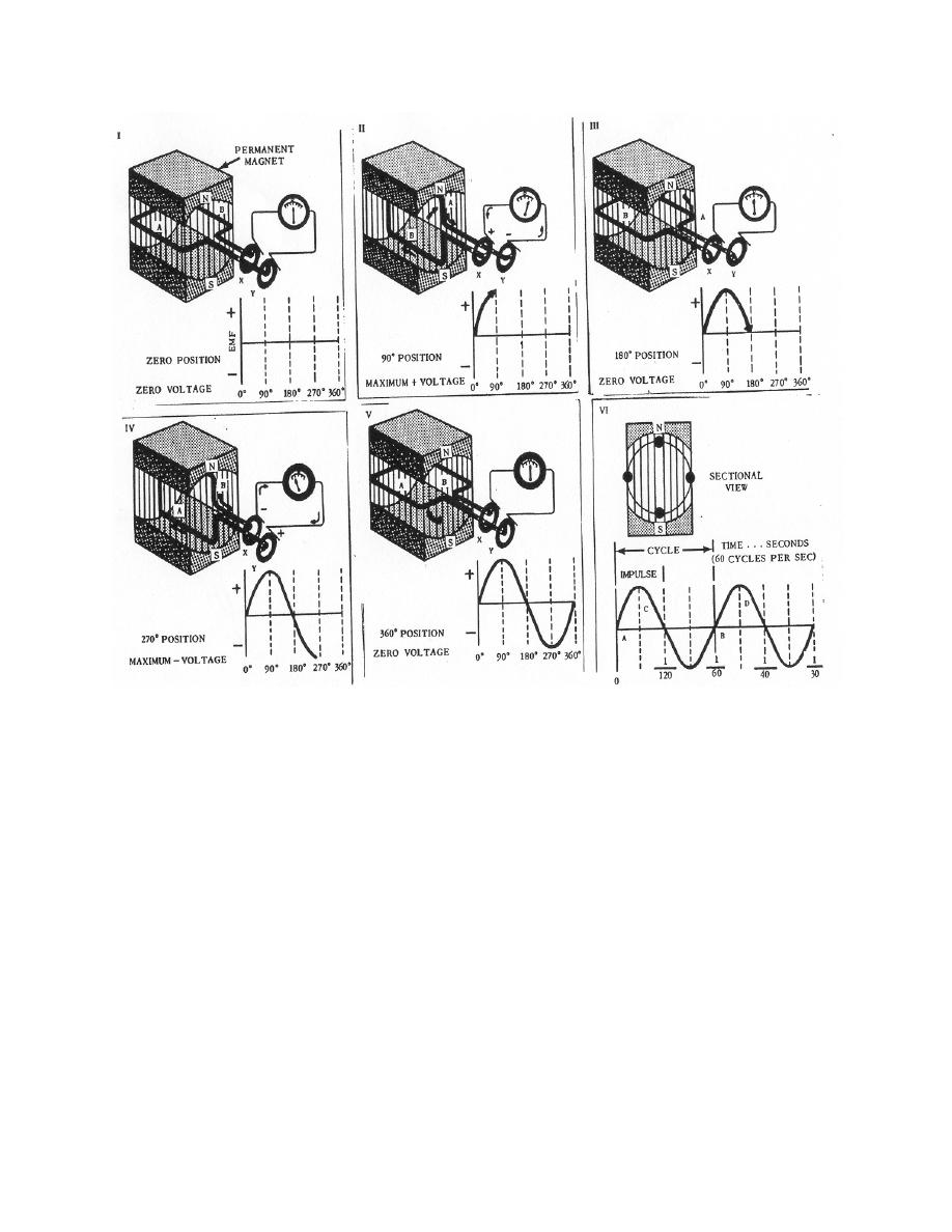
Figure 2-12. A simple alternating current generator.
b. The magnitude of the induced voltage as the coil rotates in the magnetic field
may be plotted as a curve. As the armature moves parallel to the magnetic field, no
lines of force are being cut and no EMF is being induced (I, figure 2-12). As the
armature advances toward the 90 position (II, figure 2-12), it cuts more and more lines
of force. When the conductor has moved through a 90 angle, the armature moves
perpendicular to the magnetic lines of force and cuts the maximum number. At this
point, a maximum voltage is induced in the positive direction. At the 180 position (III,
figure 2-12), the armature has made one-half revolution; since it is again moving parallel
to the magnetic field, there is no induced voltage. The armature again cuts the field at
right angles (IV, figure 2-12); however, the lines of force being cut are in the opposite
direction as before, reversing the induced voltage and giving a maximum negative
voltage. The armature completes the cycle (V, figure 2-12), returns to its original zero
position, and starts again the same series of changes.
MD0950
2-19

 Previous Page
