
opposed, the current is reversed in direction. The repulsion again exists between the
two magnetic fields, causing the rotating armature to make another half-turn. In order to
keep the armature turning steadily, this keeps occurring.
Section VI. ELECTRICAL DEVICES
2-25. CURRENT-MEASURING DEVICES
A magnetic field set up by current flowing in a conductor reacts against an
external field. This is the basic principle utilized in the construction of current-measuring
devices.
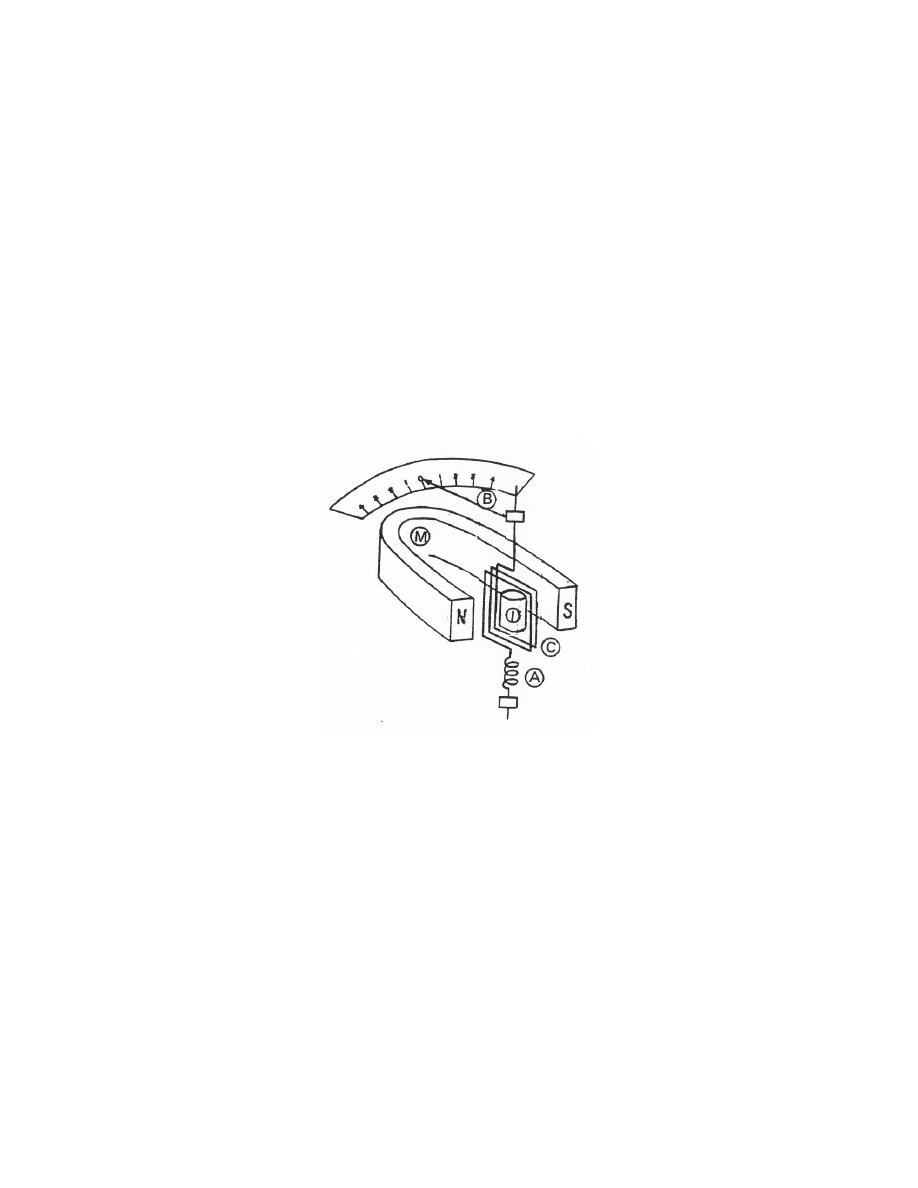
a. The d'Arsonval galvanometer (figure 2-14), the basic current- measuring
device, consists of a pivoted coil of fine wire suspended between the poles of a
permanent horseshoe magnet. Attached springs keep the coil in a zero or neutral
position when no current flows.
Figure 2-14. Galvanometer. A coil of wire (C) is suspended
between the north and south poles of a magnet (M); the coil
is attached to springs (A); a needle (B) indicates the magnitude
of the current on a scale. An iron core (I) makes the magnetic
field more uniform.
(1) When direct current passes through the coil, it becomes an
electromagnet; its poles are repelled by the like poles of the permanent magnet,
causing a twisting effect to be exerted on the coil against the resisting force of the
supporting springs. When the circuit is opened, the coil returns to its original or zero
position. The angle through which the coil turns is proportional to the strength of the
current. Whenever the coil moves on its axis, a small pointer moves across a calibrated
scale, indicating the current strength.
MD0950
2-22

 Previous Page
