
b. Place the test films on the illuminator.
c. Look for the images of wires on the tomographic scale to show varying
degrees of focus. The focus will decrease on either side.
d. Determine the distance to both sides of the cut plane where the wire images
remain in reasonable focus.
NOTE:
This is the thickness of the cut plane (see figure 6-9).
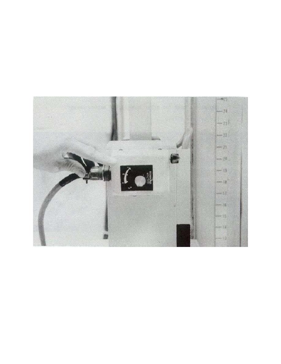
Figure 6-9. Test for all section thickness selections (example of 4 here).
e. Record the value on the data form.
f. Perform this subjective test. Since it is difficult to set specific limits on the
thickness of the cut plane, refer to the equipment manufacturer's specifications and
compare your results with them. One thing you can rely on is that as the exposure
angle increases, the thickness of the cut plane should decrease.
MD0062
6-16

 Previous Page
