
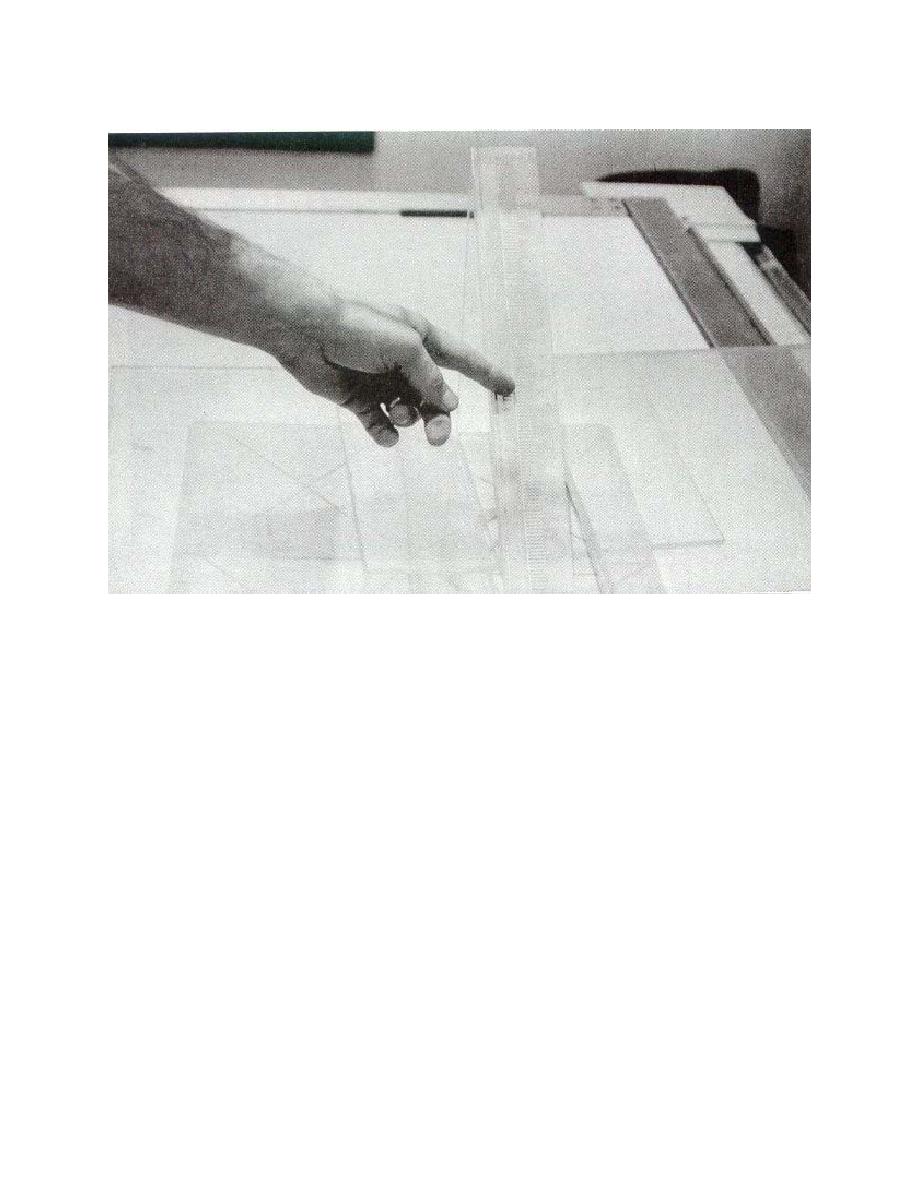
Figure 6-12. Test wedge is to center of upper left quadrant.
NOTE:
For linear systems, the wedge scale should be parallel to the direction of the
tube travel.
e. Place the Plexiglas attenuator blocks on the sides of the wedge.
f. Select:
(1)
Tomographic motion.
(2)
Sweep speed.
(3)
Exposure angle.
NOTE:
For ease in the test interpretation, the largest exposure angle should be used.
g. Set the cut level indicator at 12 cm (see figure 6-13).
MD0062
6-19

 Previous Page
