
c. Center (with respect to the tomographic field) two spacer blocks with the
resolution test object on top of them on the tabletop.
NOTE:
For linear systems, orient the resolution test object so that the slope of the
wire mesh patterns is perpendicular to the direction of the tube travel.
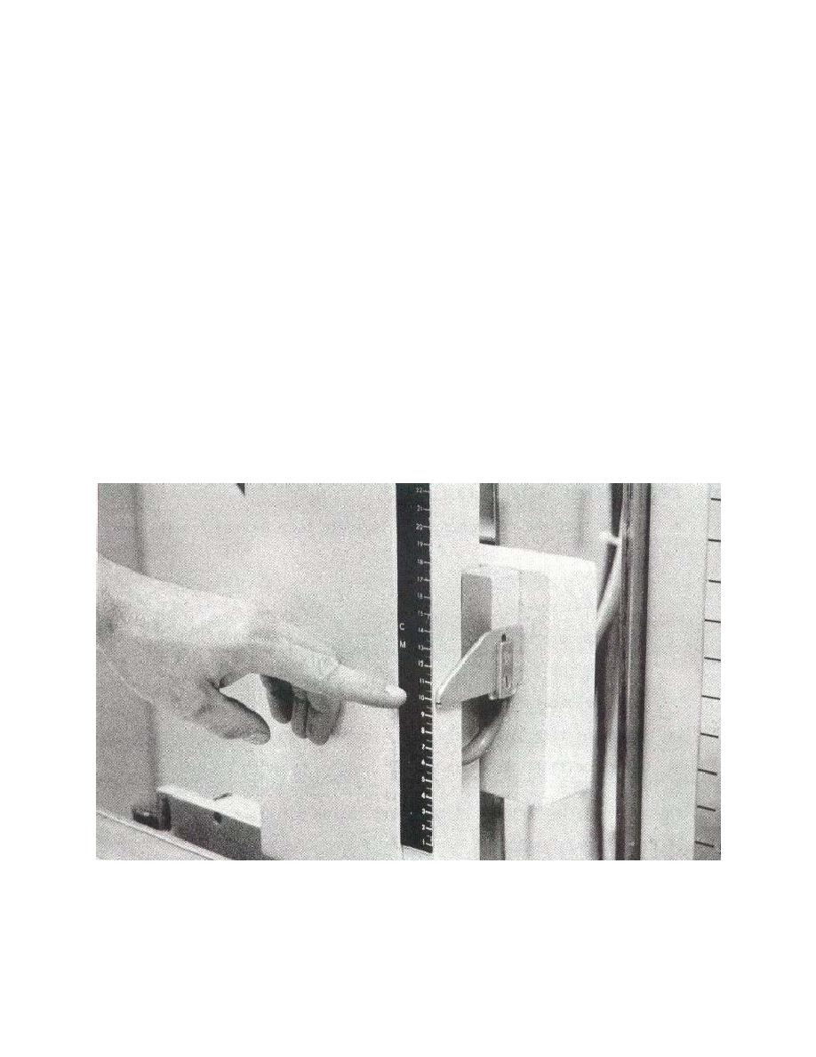
d. Select the cut level of 10.5 cm (see figure 6-15).
e. Set the control panel to 60 kVp and 20 mAs approximately.
f. Insert the 8- x 10-inch cassette into the Bucky tray (see figure 6-16).
g. Adjust the beam restriction system to an 8 x 10 field.
h. Make the tomographic exposure.
i.
Process the test film.
j. Repeat the test procedure for other tomographic motion, sweep speed, and
exposure angles.
Figure 6-15. Selecting cut level moving up to 10.5 cm.
MD0062
6-24

 Previous Page
