
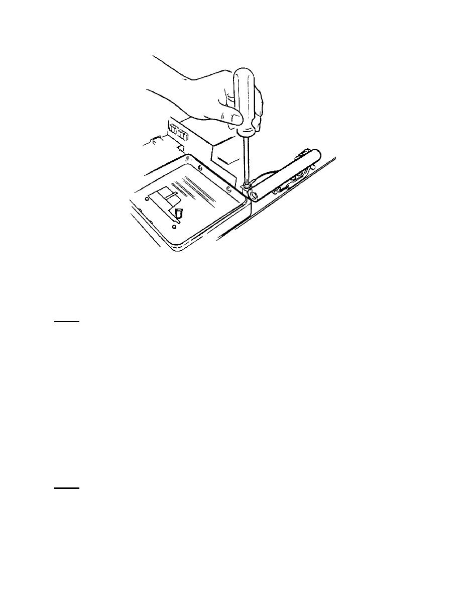
Figure 2-10. Paddle tray test load resistor disconnect.
c. Remove the Defibrillator Beeper.
NOTE:
The beeper connector is located under the paddle tray, so remove the paddle
tray before replacing the defibrillator beeper. Refer to paragraph 2-9b.
(1)
Disconnect the 2-pin connector located under the paddle tray (figure 2-11).
(2)
Remove the two screws which hold the beeper mounting bracket in place.
(3) Place your first and second fingertips under the beeper mounting plate.
Use thumb pressure to press down on the beeper spring tabs encircling the edge of the
seating hole. The beeper should release easily.
d. Remove the Switch Plate.
(1) Remove the two mounting screws on board 590235 and carefully lift the
board away (figure 2-12).
NOTE:
The right end of the 590235 board seats into a small slot in the mother board.
Be sure to reseat it into the slot when remounting the board.
(2) Disconnect the 2-pin plug connecting the battery indicator assembly to the
mother board.
MD0362
2-53

 Previous Page
