
a. Nonpressure Type Vacuum Breaker. The nonpressure type vacuum
breaker is illustrated in figure 6-13. This type of vacuum breaker must always be
installed on the atmospheric side of the fixture valve. The installation of a nonpressure
type vacuum breaker on the atmospheric side of the last control valve is always
preferred over the use of a pressure type vacuum breaker (b, below). In this instance,
the device is installed on a flushometer valve water closet with the flushometer valve
located directly above the vacuum breaker and the flood level rim of the water closet
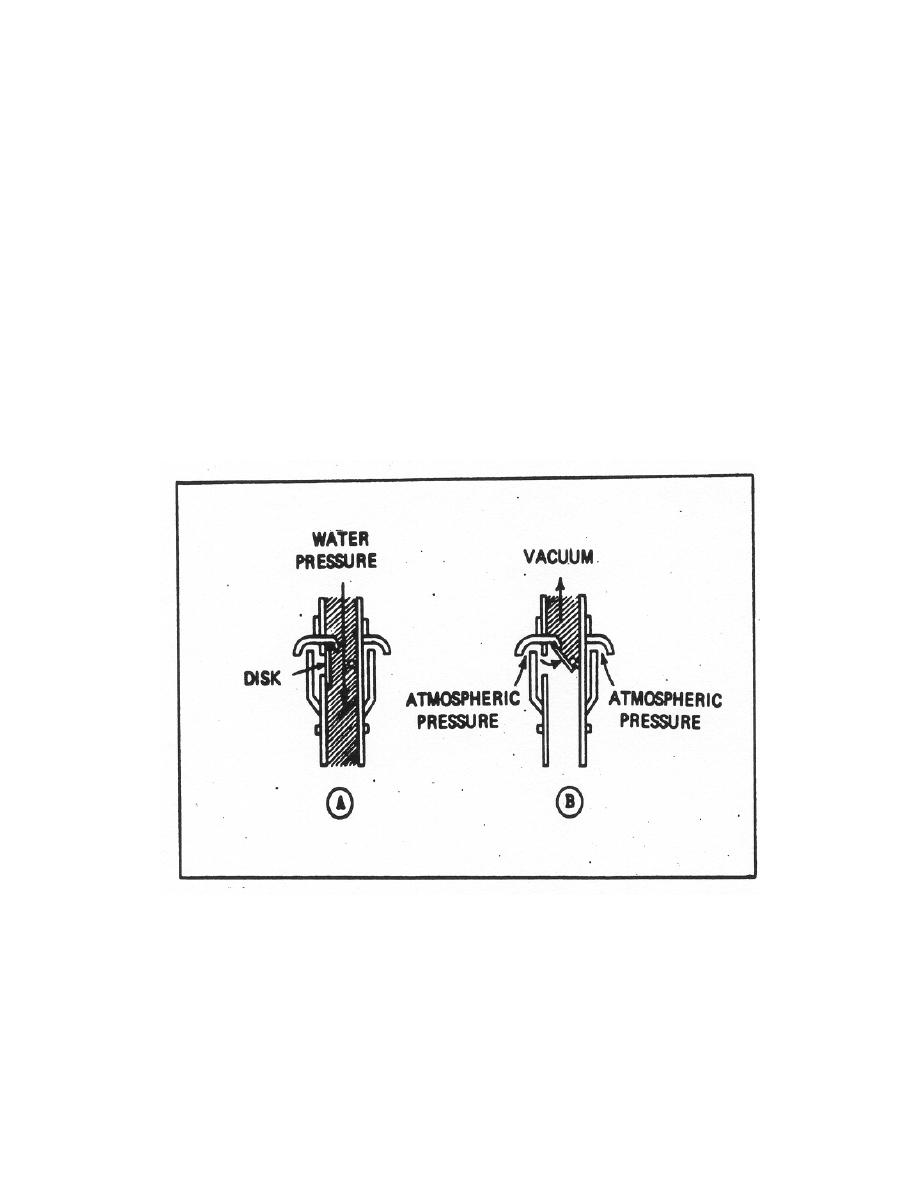
located at least 6 inches below the vacuum breaker. When the flushometer valve is
operated (see figure 6-13 A), the flow of water is downward and the disk is in the
normal, vertically seated position, preventing water from spiIIing out of the pipe. If a
negative pressure should develop on the supply Iine to the fixture, atmospheric
pressure would be exerted on the disk and within the supply Iine above the flood level
rim (see figure 6-13 B), thus preventing backsiphonage from the water closet. The
vacuum breaker IS NOT designed to provide protection against backflow resulting from
BACKPRESSURE (such as a direct connection with a system under higher pressure)
and should not be installed where backpressure may occur.
Figure 6-13. Nonpressure type vacuum breaker.
b. Pressure Type Vacuum Breaker. The pressure type vacuum breaker is
designed to remain operable after having remained under hydrostatic pressure for
extended periods of time. This type of vacuum breaker works on the reverse principle
of the nonpressure type, in that the moving parts do not complete a full cycle of
operation each time the fixture or supply line is used. The principle of operation is
MD0160
6-18

 Previous Page
