
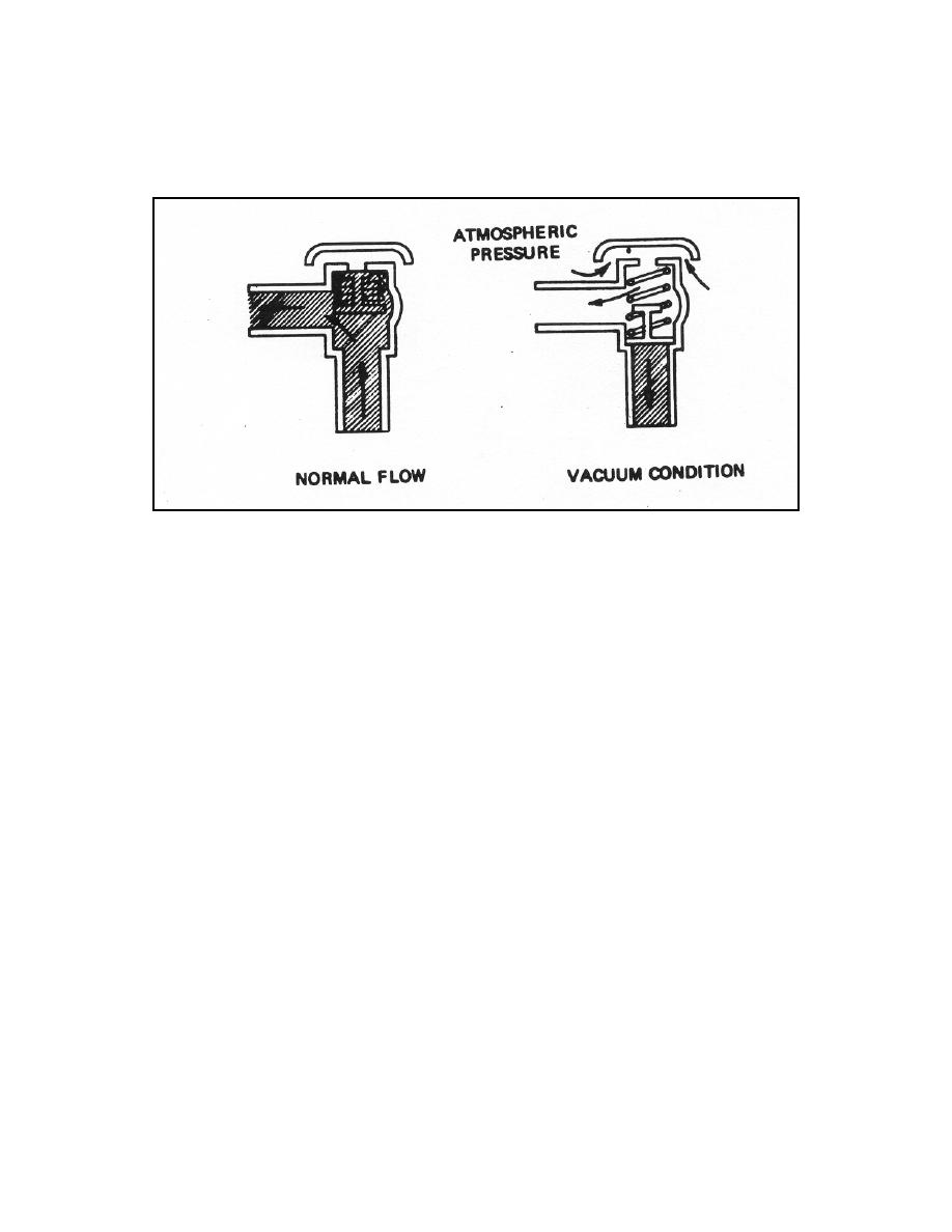
shown in figure 6-14. The device is designed to open permitting the admission of air to
satisfy the vacuum when a negative head occurs in the supply Iine. It does not provide
protection against backflow resulting from BACKPRESSURE.
Figure 6-14. Pressure type vacuum breaker.
6-12. REDUCED PRESSURE BACKFLOW PREVENTER
The pressure and nonpressure type vacuum breakers are designed to prevent
backsiphonage only and cannot be installed where backpressures are Iikely to occur. In
situations where it would be extremely difficult to provide a physical break between two
systems and where backpressures can be expected, a reduced pressure backflow
preventer can be used. This device consists of two hydraulically or mechanically
loaded, pressure-reducing, check valves with a pressure regulated relief valve located
between the two check valves as shown by figure 6-15. Flow from the left enters the
central chamber through check valve A. The pressure exerted by this check valve
lowers the pressure in the central chamber. Check valve B is Iightly loaded in the
direction of flow. In the event that the pressure increases downstream from the device,
causing backpressure, check valve B closes, thus preventing backflow. Because all
valves may leak as a result of wear or obstruction, the protection provided by the check
valves is not considered sufficient; therefore, a relief vaIve C is provided in the reduced
pressure zone- (centraI chamber). This relief valve is preset to open at a lower
pressure than check valve A. Therefore, if for some reason (an obstruction, wear, and
so forth) check valve B should permit a reverse flow to enter the central chamber, the
relief valve A wiII open. This wiII release the reverse flow to the atmosphere.
MD0160
6-19

 Previous Page
