
b.
Delivery Circuit. The selected mixture of air and oxygen is delivered to
the ventilator's inlet manifold through a wing nut mounted atop the unit.
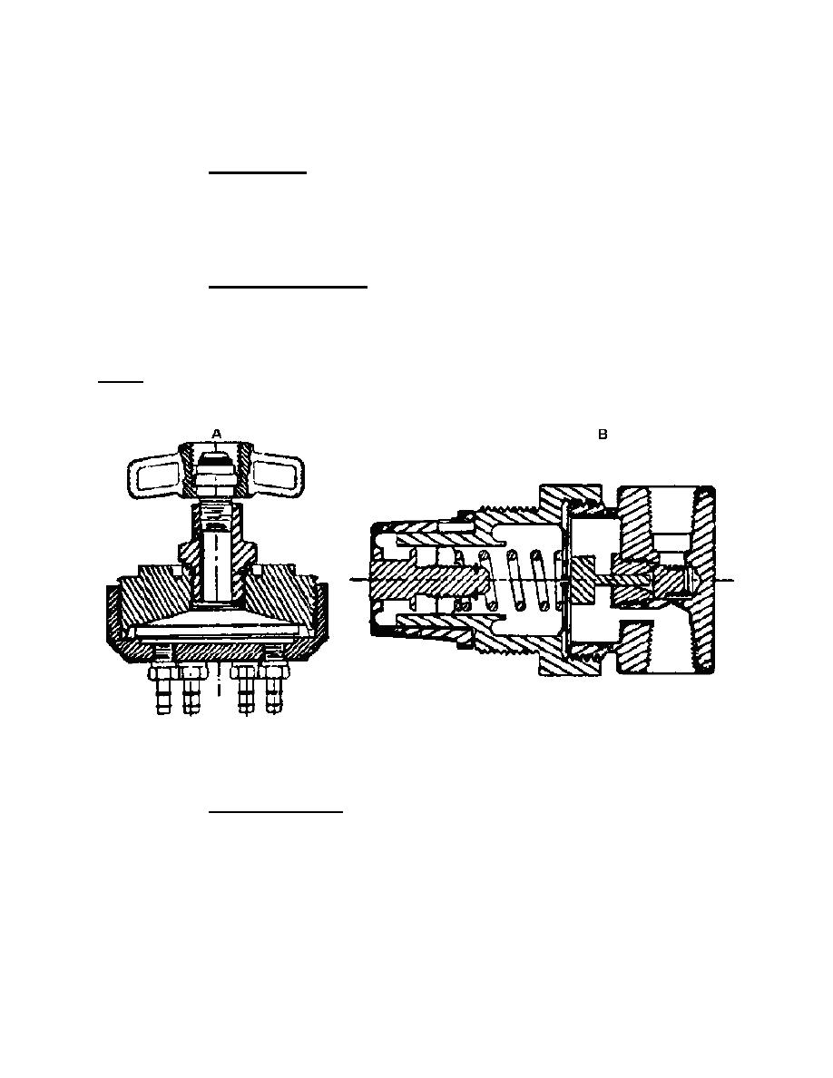
(1) Inlet manifold. The inlet manifold, shown at A in figure 1-3, contains a
five micron sintered bronze filter and has six outlet ports which direct gas mixtures to the
functional components of the ventilator. The pressure gauge indicates source-gas
pressure to the ventilator from one outlet of the inlet manifold. The green wedge on the
dial indicates the mandatory pressure range of 45 to 55psi.
(2) Flow-control regulator. A second outlet from the inlet manifold is
connected to the flow-control regulator shown in figure 1-3 "B." One outlet from the
regulator is connected to a gauge calibrated in liters-per-minute (lpm) flow. The other
regulator outlet delivers the gas mixture to a tee fitting.
NOTE:
Do not attempt to service the flow-control regulator. It is set at the factory and
is not to be disassembled.
Figure 1-3. Inlet manifold (A) and flow-control regulator (B).
(3) Flow-bypass valve. One outlet from the tee fitting is connected to the
flow-bypass valve shown in figure 1-4 and is used in conjunction with the nebulizer
control. Its function is to bypass gas flow around the nebulization control to the auxiliary
jet socket. It also serves as a pressure governor to maintain calibrated flow to the
breathing circuit. It consists of an adjustable orifice, a plunger, and a spring.
MD0355
1-5

 Previous Page
