
(1)
Loosen, do not remove, the four screws on the top trim band.
(2)
Remove the screws labeled A, B, C, and D in the figure.
(3)
Lift the top cover and pull it forward.
(4)
Remove the five screws from the cone track and remove the cone track.
(5)
The lamp switch may now be removed from the cover and reconnected.
(6)
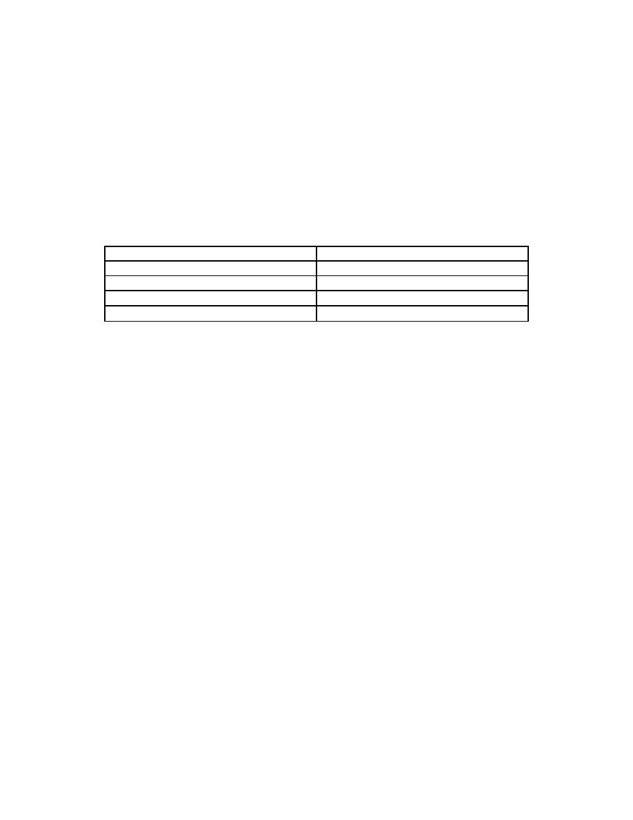
Set the switches on the logic PCB as given in the following chart.
SW2-1
OFF
SW3-1
OFF
SW2-2
OFF
SW3-2
OFF
SW2-3
OFF
SW3-3
OFF
SW2-4
OFF
SW3-4
OFF
SW2-5
OFF
SW3-5
OFF
e. Collimator-Tilt Switch Checkout. Position the tilt switch at 0 degrees,
horizontal. Angle the collimator to a 0 degrees beam-down position. Slowly angle the
collimator +20 degrees toward a beam-left position and back to -20 degrees toward a
beam-right position. Light-emitting diode four must be on at 0 degrees and remain
on for +11 degree and -11 degree angles.
(1) Angle the collimator to a +90 degree beam-left position and slowly angle
it to 20 degrees down below horizontal (+70 degrees from vertical). Light-emitting diode
must be on at +90 degrees and remain on for 11 degrees below horizontal (+79 degrees).
(2) Angle the collimator to a -90 degree beam-right position and slowly
angle it to 20 degrees down below horizontal (-70 degrees from vertical). Light-emitting
diode-5 must be on at -90 degrees and remain on for 11 degrees below horizontal
(-79 degrees). If the collimator tilt switch does not check out, refer to master board
schematic 70-08009 in the service literature.
f. Table-Tilt Switch Checkout (for tilting tables only). Remove the jumper
between TS2-5 and TS2-10. Angle the collimator to 0 degrees beam-down. Angle the
table to 0 degrees horizontal and slowly tilt it to +20 degrees and then -20 degrees.
Light-emitting diode-4 1-14, must be on with the table at 0 degrees and remain on
for +11 degrees and -11 degrees from horizontal.
(1) Position the table at +90 degrees upright (usually about an actual +85
degrees) and angle the collimator to a +90 degree (LED-1 "ON") beam-left position.
Slowly tilt the table 20 degrees down from the maximum upright position (+70 degrees).
Light-emitting diode-7 must be ON at a maximum upright and remain ON until the table
is angled down to +79 degrees. (Light-emitting diode-1 will also be ON).
MD0351
1-37

 Previous Page
