
(2) If the cassette holder is on the wall adjacent to the foot-end of the table,
this requires the collimator to be at -90 degrees beam-right.
(a)
Light-emitting diode-5 on the logic PCB must be ON.
(b) Set SW2-5 "ON" on the logic PCB to select right-wall operation.
NOTE:
If the wall-mounted cassette holder is on the wall adjacent to the head end of
the table, leave SW3-5 ON and SW2-5 OFF. If it is on the wall adjacent to
the foot-end of the table, leave SW3-5 OFF and SW2-5 ON. Only one switch
is to be closed at a time.
(3) Move the collimator horizontally until the distance from the source (focal
spot) to image receptor (film in cassette) is at a 72-inch SID. Slowly move the collimator
to a greater and then to a lesser SID while measuring the actual SID. The 72-inch
indicator on the collimator must be ON at a measured 72-inch SID and must switch OFF
at a maximum of 72.75 inches and OFF again at a minimum of 71.25 inches SID.
(4) Move the collimator horizontally to a 40-inch SID, and slowly move the
collimator to a greater and then to a lesser SID. The 40-inch indicator on the collimator
must be ON at a measured 40-inch SID and must switch OFF at a maximum of
40.40 inches and OFF again at a minimum of 39.60 inches SID.
i. Tilting Table Receptor Light-Emitting Diode Signal Checkout (for
tilting tables only). Angle the table to a full upright position. Angle the collimator
beam-left to aim the X-ray beam at the upright table cassette tray. Light-emitting
diode-7 on the logic PCB must be ON.
(1) Move the collimator horizontally to a 40-inch SID, and slowly move the
collimator to a greater and then to a lesser SID. The 40-inch indicator on the collimator
must be ON at a measured 40-inch SID and must switch OFF at a maximum of
40.40 inches and OFF again at a minimum of 39.60 inches SID.
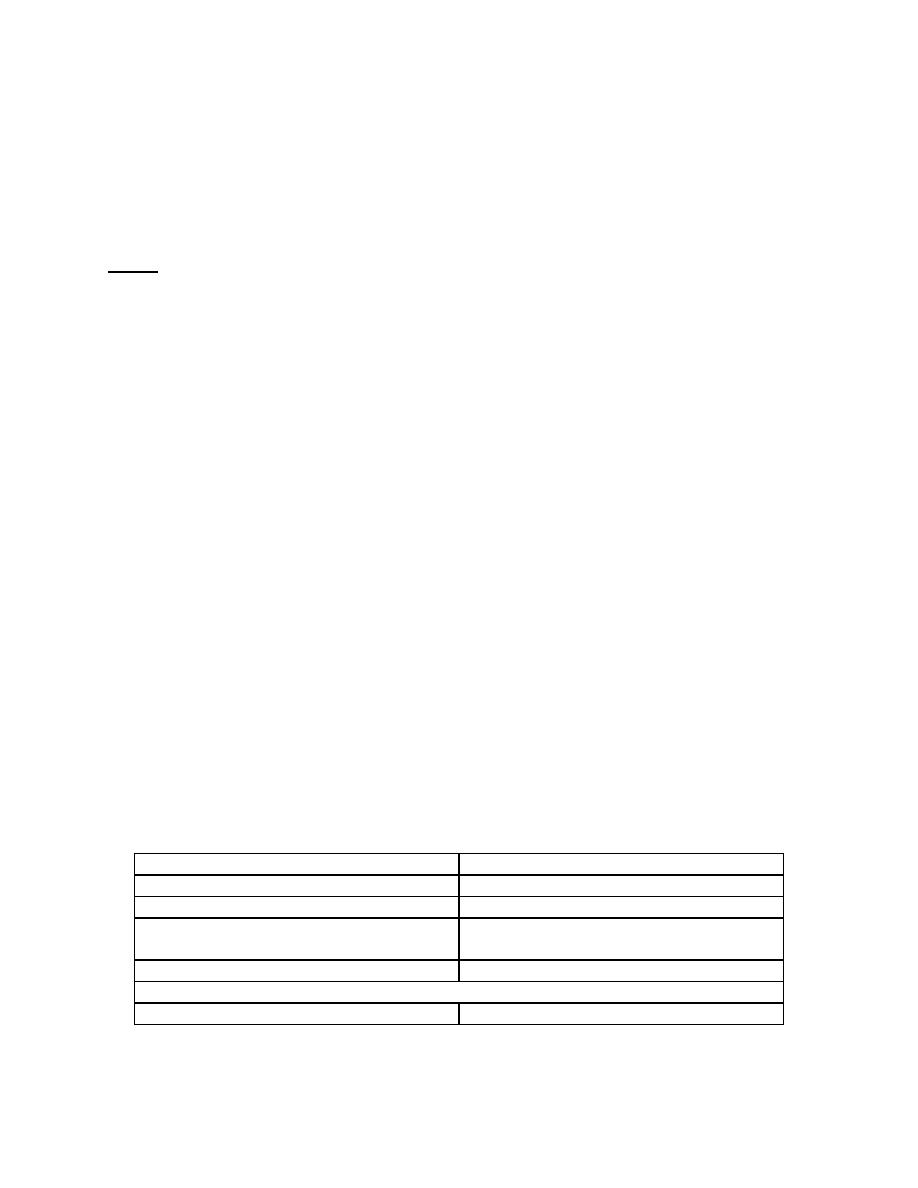
j. External Indicated Radiation Signals Checkout (tilting or non-tilting tables).
(1)
Set the switches on the logic PCB as given in the following chart.
SW3-1
OFF
SW4-1
OFF
SW3-2
OFF
SW4-2
OFF
SW3-3
OFF
SW4-3
OFF
SW3-4
OFF
SW4-4
OFF
SW2-5 ON
SW3-5 OFF (Beam-Right Operation)
OR
SW2-5 OFF
SW3-5 ON (Beam-Left Operation)
MD0351
1-41

 Previous Page
