
(3)
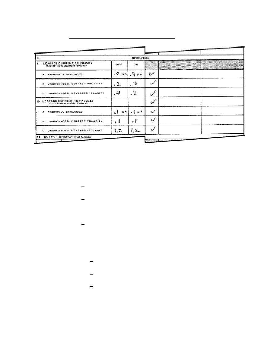
Section II, operation (blocks 9A through 9C). Refer to figure 2-7.
Figure 2-7. DA Form 5624-R, blocks 9 and 10.
(a) Measure and record the leakage current to the chassis in the
equipment's ON and OFF positions.
1 Set the mode switch on the safety analyzer to CASE LEAKAGE.
2 Connect a Kelvin cable to the red rear panel jacks. The current
is disabled in this mode so you can leave the cable connected for both resistance and
leakage tests.
3 Connect the alligator clip of the Kelvin cable to a grounded point
on the case of the unit under test (UUT). If you leave the clip in place after making the
ground resistance measurement, you can be sure you have the clip on a grounded point
of the case. Make the following case-leakage measurements for the various line
conditions.
a Unit Under Test power on and off.
b Normal and reverse polarity.
c
Closed and open ground.
(b) Circle any unacceptable values.
(c)
If no action is required, place an "X" or "√" in the "ok" column.
MD0358
2-10

 Previous Page
