
NOTE:
Check the calibration of the flow test device (P/N 4418) for zero. The
calibration screw is either located at the 12 o'clock position on the back of the
gauge (0-40cmH20) or at the 12 or 3 o'clock position on the front of the
0-120cmH2O gauge.
(2)
Flow system.
(a) Disconnect the green patient-breathing tube from the outlet of the
500cc in-line nebulizer.
(b) Install the flow test device (P/N 4418) to the nebulizer outlet with the
orifice pointing away from the nebulizer.
(c) The flow is determined indirectly as a proportional function of
measured backpressure (orifice).
(d) Rotate the flow control clockwise for 10 lpm. Pressure on the flow
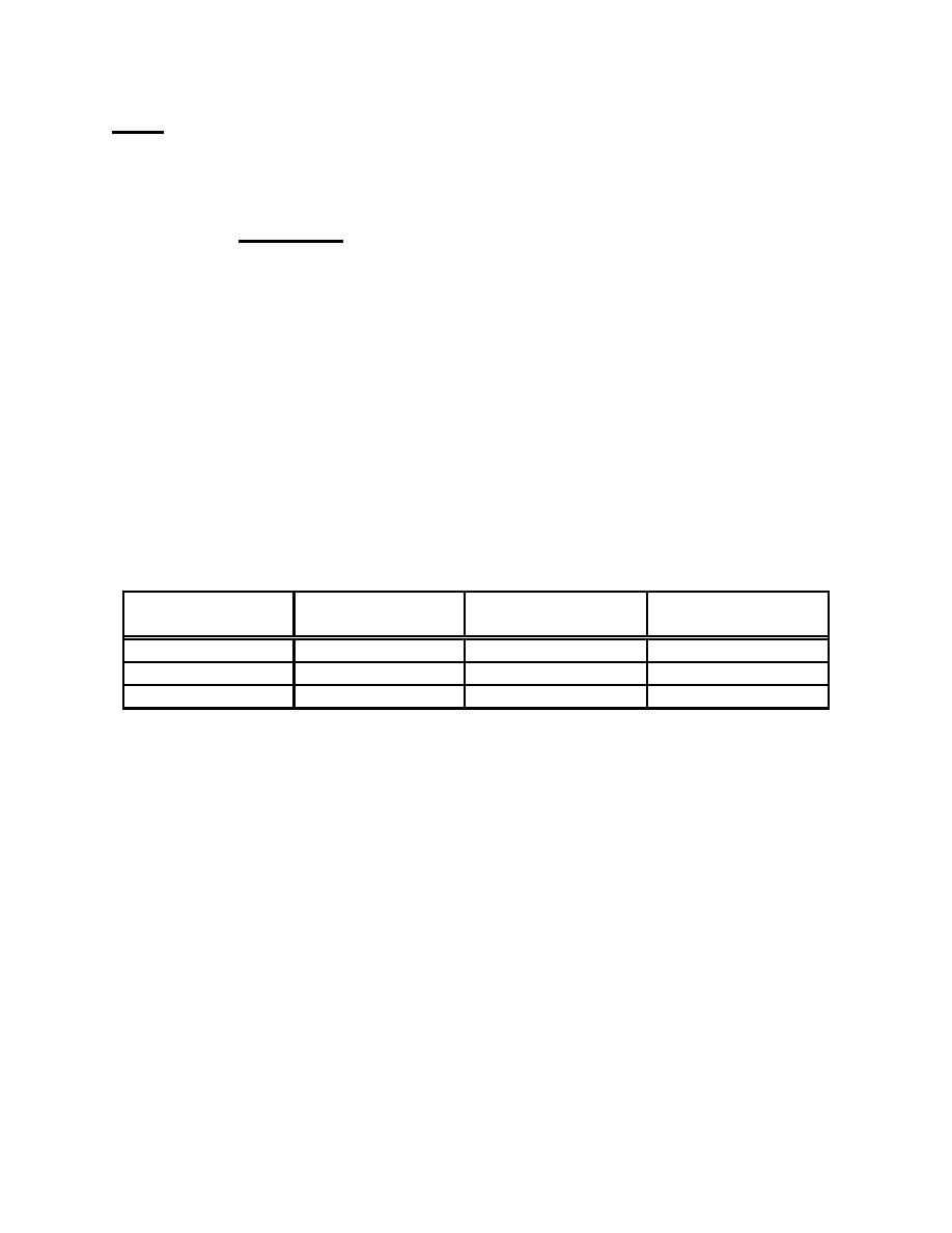
test device should be 8cmH2O. A range of acceptable flow parameters is shown in the
chart below. If the pressure registered on the flow test device is not within the specified
range, refer to paragraph (e) below for flow adjustments. Flow is measured as
backpressure (cmH2O) on the flow test device (P/N 4418). Refer to Table 2-3.
Actual Flow
Recommended
Minimum
Maximum
+ 2 LPM
Acceptable
10 lpm
8cmH2O
6 1/2cmH2O
12 1/2cmH2O
15 lpm
17cmH2O
14cmH2O
21 1/2cmH2O
20 lpm
29cmH2O
24 1/2cmH2O
34cmH2O
Table 2-3. Flow test device pressures.
(e) Corrections of flows are made by using the 3/32-inch Allen wrench
to rotate the adjusting screw on the end of the bypass valve (refer to figure 2-2, point A).
A clockwise rotation of this screw will decrease the backpressure (lower gauge reading).
A counterclockwise rotation will increase backpressure (higher gauge reading). You
may have to set a minimum or maximum flow at one setting to achieve an acceptable
range at another setting.
(f) If the flow from the Babybird ventilator falls within the acceptable
ranges at 10, 15, and 20 lpm, disconnect the flow test device and reconnect the green
patient-breathing tube to the 500cc nebulizer.
(g) If the flow/backpressure parameters cannot be satisfactorily
adjusted, follow the procedures in Table 2-4 to troubleshoot the flow system.
MD0355
2-9

 Previous Page
