
(13) Check the lift to ensure that it is blocked to its highest position. Make
adjustments as required.
(14) Engage the chain drive upon the sprockets and replace the three
mounting screws. Pull the motor to tighten the drive chain while tightening the mounting
screws. Refer to figure 3-4.
(15) Remove the wood block from the pantograph arms.
The lift must not over travel to the point where the pantograph arms
CAUTION:
close up under power. Otherwise serious damage will occur. There
should be at least 5/8 inch of space remaining between the parallel
pantograph arms when the motor stops at the low lift position.
(16) Run the lift down to check the lower extreme position.
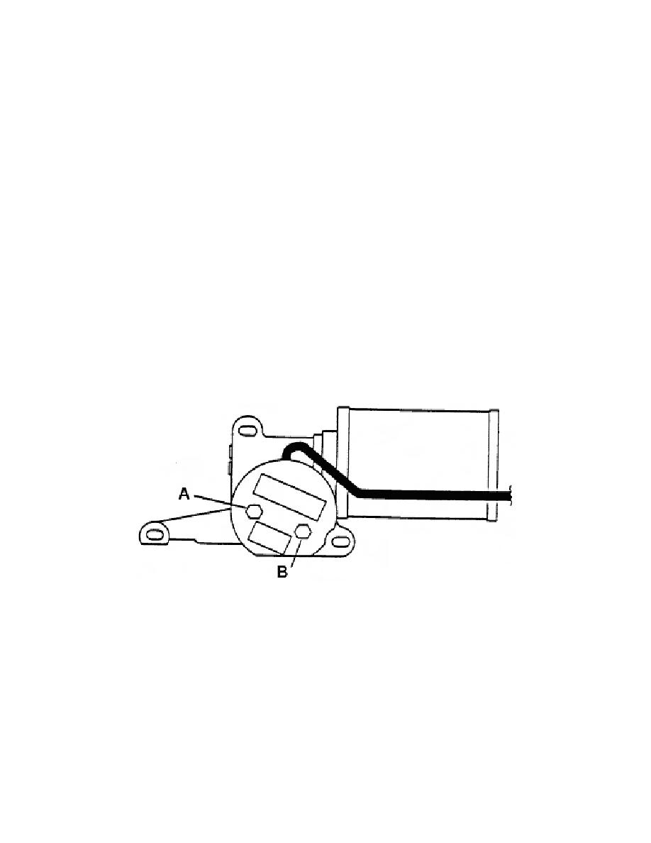
(17) Adjust the height of the lift using a 7/16 inch open-end or box wrench.
Loosen the locknut on the adjusting screw (Switch "A" on PLR-200) (refer to figure 3-7)
and turn clockwise (refer to figure 3-4) to raise the lower limit of the lift. Turn
counterclockwise to decrease the lower limit of the lift. Each full turn of the adjusting
screw changes the lift height 9/16 inch.
Figure 3-7. Switches "A" and "B" on PLR-200.
(18) Retighten the lock nut after you complete adjusting the adjusting screws.
(19) Reinstall the junction box cover.
(20) Place the main cover over, reinstall the rotation lock pedal, and tighten
the 3/4 inch nut.
(21) Replace the four screws securing the base cover to the lift.
MD0373
3-9

 Previous Page
